Semiconductor device and manufacturing method thereof, and electronic device
A semiconductor and device technology, applied in the field of semiconductor devices and their preparation, can solve problems such as low withstand current, and achieve the effects of reducing leakage, improving ESD voltage withstand and current withstand capabilities, and improving ESD performance
- Summary
- Abstract
- Description
- Claims
- Application Information
AI Technical Summary
Problems solved by technology
Method used
Image
Examples
Embodiment 1
[0032] Below, will refer to figure 1 , figure 2 The semiconductor device manufacturing method of the present invention is described in detail.
[0033] Such as figure 1 As shown, a prior art semiconductor device includes a semiconductor substrate 100 . The semiconductor substrate 100 may be at least one of the materials mentioned below: silicon, silicon-on-insulator (SOI), silicon-on-insulator (SSOI), silicon-germanium-on-insulator (S-SiGeOI), insulator Silicon germanium-on-insulator (SiGeOI) and germanium-on-insulator (GeOI), etc. The semiconductor substrate is preferably a P-type substrate doped with B or Ga elements. An N well 105 is then formed on the P-type substrate.
[0034] The N well 105 can grow a layer of SiO on the surface of the P-type substrate 2 , in SiO 2 Coat photoresist for photolithography to form N-well doped window, and then use HF to etch SiO at the window 2 And remove the glue. At this time, N-type impurities can be implanted into the window to...
Embodiment 2
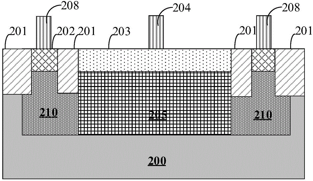
[0054] Below, will refer to figure 2 The semiconductor device of the present invention will be described in detail.
[0055] Such as figure 2 As shown, the semiconductor device of the present invention includes a semiconductor substrate 200 . The semiconductor substrate may be at least one of the materials mentioned below: silicon, silicon-on-insulator (SOI), silicon-on-insulator (SSOI), silicon-germanium-on-insulator (S-SiGeOI), silicon-on-insulator Silicon germanium (SiGeOI) and germanium on insulator (GeOI), etc. The semiconductor substrate is preferably a P-type substrate doped with B or Ga elements.
[0056] A shallow trench isolation (STI) structure 201 may also be included on the semiconductor substrate. Generally, the basic process of forming the STI structure 201 is as follows: 2 O or O 2 The substrate is thermally oxidized under air flow to form SiO 2 Thin layer, about 20nm thick. followed by SiO 2 On the thin layer, silicon nitride with a thickness of abo...
Embodiment 3
[0064] The present invention also provides an electronic device, which includes the semiconductor device described in Embodiment 2 and an electronic component connected to the semiconductor device.
[0065] Wherein the semiconductor device includes: a semiconductor substrate; a first well region with a first conductivity type formed in the semiconductor substrate; a well region with a first conductivity type formed outside the first well region in the semiconductor substrate a second well region of the first conductivity type; a first diffusion region of the second conductivity type formed in the first well region; a second diffusion region of the first conductivity type formed in the second well region, Wherein the ion concentration of the first conductivity type in the first well region is lower than the ion concentration of the first conductivity type in the second well region. The first diffusion region of the second conductivity type and the first well region of the first...
PUM
 Abstract
Description
Claims
Application Information
 - R&D
- Intellectual Property
- Life Sciences
- Materials
- Tech Scout
- Unparalleled Data Quality
- Higher Quality Content
- 60% Fewer Hallucinations
Browse by: Latest US Patents, China's latest patents, Technical Efficacy Thesaurus, Application Domain, Technology Topic, Popular Technical Reports.
© 2025 PatSnap. All rights reserved.Legal|Privacy policy|Modern Slavery Act Transparency Statement|Sitemap|About US| Contact US: help@patsnap.com


