
Plasmatron type waterfall water treatment device

A plasma tube and treatment device technology, applied in the field of flowing water treatment devices, can solve problems such as unsuitable water treatment for flowing water, limited water treatment capacity, difficulty in forming plasma, etc.

Inactive Publication Date: 2017-01-04
苏州超等医疗科技有限公司
View PDF1 Cites 0 Cited by
  • Summary
  • Abstract
  • Description
  • Claims
  • Application Information

AI Technical Summary

Problems solved by technology

[0004] At the same time, there is also a method of combining dielectric barrier discharge and ultraviolet light for water treatment, using electric discharge inside the dielectric barrier discharge tube containing wastewater to generate oxidative components and ultraviolet rays, and disperse the generated oxidative components into the water , to achieve the purpose of treatment, and at the same time use ultraviolet radiation to treat the water body, but the treatment capacity of this method is limited by the size of the dielectric barrier discharge tube, and it is necessary to ensure a certain water body residence time, which is not suitable for flowing water water treatment
[0005] At present, there is no large-scale plasma water treatment equipment, because the high voltage of the plasma and the high voltage discharge distance of the water body need to be accurate to about 1cm, but the accuracy of this distance cannot be controlled due to the fluctuation of the water body, so it is very difficult to form large-scale water surface plasma
To make matters worse, the water fluctuations can cause a short circuit after contacting the high voltage electrodes, thus destroying the power supply.

Method used


Image

  • Plasmatron type waterfall water treatment device

Examples


Embodiment Construction

[0010] In order to deepen the understanding of the present invention, the present invention will be further described in detail below according to the accompanying drawings.

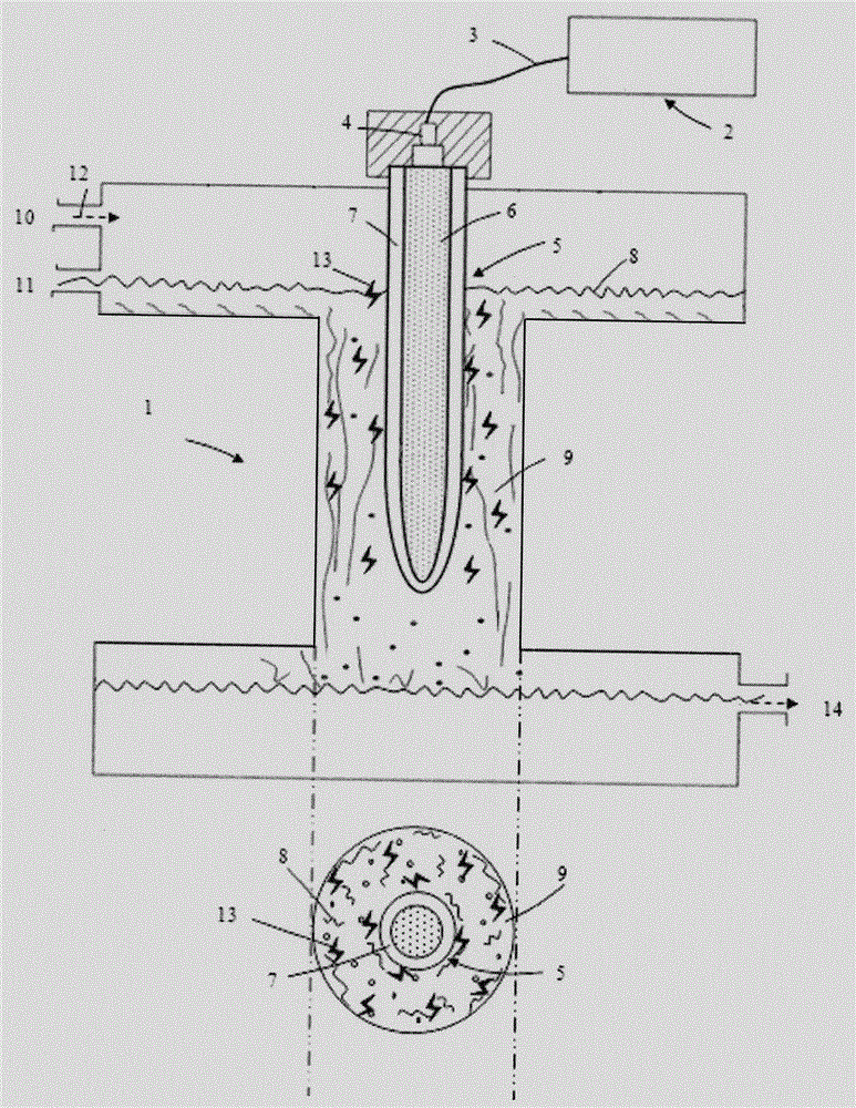
[0011] figure 1 Among them, the plasma tube type waterfall water treatment device of the present invention consists of a water collection tank 1, a plasma generator 2, a wire 3, a high-voltage electrode 4, a quartz glass tube 5, a vertical tube 9, an air inlet 10, a water inlet 11, a water outlet 14, etc. Composition, the plasma generator 2 is connected to the high-voltage electrode 4 through the wire 3, the high-voltage electrode 4 is connected to the quartz glass tube 5, the quartz glass tube 5 is located at any position of the water collection tank 1, the water inlet 11 and the air inlet 10 are in the same water collection tank 1 side, the water outlet 14 is located on the other side of the water collection box 1, and the vertical pipe 9 is placed in the water collection box 1.

[0012] Preferably, t...


PUM


Abstract

A plasmatron type waterfall water treatment device comprises a water collecting tank, a plasma generator, a high-voltage electrode, a quartz glass tube, a perpendicular tube, a wire and the like. The plasma generator is connected with the high-voltage electrode through the wire. The high-voltage electrode is connected with the quartz glass tube. A tube body of the quartz glass tube is partly placed in the perpendicular tube. An air inlet, a water inlet and a water outlet are located in the two sides of the water collecting tank. A water body flows into the water collecting tank from the water inlet and forms waterfall type water flow from top to bottom along the perpendicular tube according to a free falling body gravity principle. Air collides with the quartz glass tube through the air inlet to generate plasmas and makes full contact with the water flow, and treatment area is enlarged; the plasmas are dispersed in water in the form of micro-bubbles, and organic matter is removed. On the other hand, the plasmas can react with water to generate active oxygen components and then act on the water body, so bacteria and algae lose a reproductive function, bacteria, algae and other microorganisms in the water body are rapidly and effectively killed, and the water treatment efficiency is remarkably improved.

Description

technical field [0001] The invention relates to the technology of plasma application in water treatment, in particular to a flowing water treatment device in which plasma high-voltage discharge acts on a vertically falling body. Background technique [0002] Common water treatment methods include sediment filtration, activated carbon adsorption, ultraviolet disinfection, mixed ion exchange, etc. With the continuous improvement of life, water eutrophication, ammonia nitrogen, phosphorus and other nutrient salt problems and the National Environmental Protection Agency's regulations on sewage Discharge standards have been raised step by step, and the "primary treatment" and "secondary treatment" water treatment technology and equipment that have been used for many years have been difficult to meet today's high turbidity and high concentration sewage treatment requirements, such as activated carbon filtration, micro Technical systems such as pore filtration and permeable membran...

Claims


Application Information

Patent Timeline
IPC IPC(8): C02F1/30C02F1/72
CPCC02F1/30C02F1/72C02F2201/002
Inventor 陈晓波施婷婷
Owner 苏州超等医疗科技有限公司
Learn More