underground dump truck
A technology of dump truck and main frame, applied in the field of mining machinery, can solve problems such as affecting the reliability and safety of vehicles, affecting the flexibility of vehicles, affecting braking safety, etc., so as to improve braking performance and use safety, good High braking effect, stiffness and strength
- Summary
- Abstract
- Description
- Claims
- Application Information
AI Technical Summary
Problems solved by technology
Method used
Image
Examples
Embodiment 1
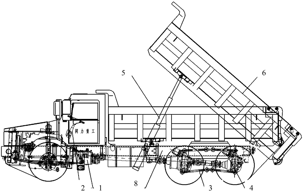
[0084] The invention provides an underground dump truck, such as figure 1 As shown, it includes: a main frame 8, which includes cross beams and longitudinal beams, and the cross beams and longitudinal beams are vertically interlaced. , using high-strength bolts to connect the beam and the left and right longitudinal beams together, so that the overall strength and rigidity of the frame are greater; the power system 1 is connected to the main frame 8; the steering system 2 is connected to the The left front outside of the main frame 8; the suspension system 3, which is connected to the bottom of the main frame 8, the front axle adopts a 6.5-ton wet brake steering axle, and the middle and rear axle adopts a 13-ton wet engineering drive axle. The middle and rear axle adopts a 25-ton balanced suspension. This structural type is widely used in automobiles and has overload capacity. For the special working conditions of underground transportation, when the total mass of the vehicle ...
Embodiment 2
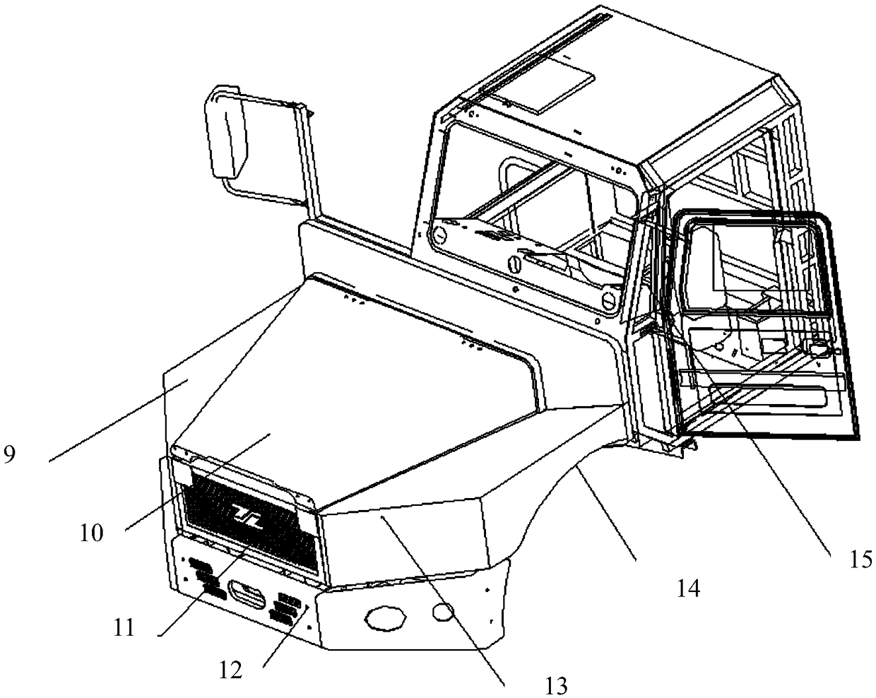
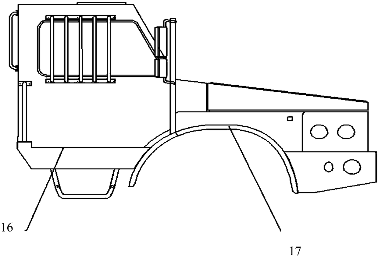
[0086] In embodiment 2, the structure is basically the same as that of embodiment 1, as figure 2 , image 3 As shown, in embodiment 2, the front cover hood 10 in the cab assembly is connected to the cab 15 by 2 hinges and 12 bolts, and the left platform 13 and the right platform 9 are respectively installed on the cab 15 by 6 bolts. On the driver's cab 15, the mask 11 is installed on the left platform 13 and the right platform 7 by 8 bolts. At the same time, these two platforms are fixed together. On the platform 9 and the cab 15, the bumper 12 is respectively installed on the left wheel arch 14 and the right wheel arch 17 through 6 bolts, and the right wing plate 16 is connected to the cab by bolts. Through the above installation and connection, the cab assembly While ensuring the functions of the cab 15, the rational arrangement and connection of the cab cover, the bumper, and the right wing panel make the cab assembly fully meet the design and use requirements.
Embodiment 3
[0088] Embodiment 3 is substantially the same as Embodiment 1, as Figure 4 , Figure 5 As mentioned above, the cab 15 is a full-frame cab 15, which is welded by a top frame 18, a left frame 19, a front frame 20, a floor frame 21, a rear frame 22, a right frame 23, and a right wing frame 24. Each skeleton unit is composed of rectangular tube welds of related sections.
PUM
 Abstract
Description
Claims
Application Information
 - R&D
- Intellectual Property
- Life Sciences
- Materials
- Tech Scout
- Unparalleled Data Quality
- Higher Quality Content
- 60% Fewer Hallucinations
Browse by: Latest US Patents, China's latest patents, Technical Efficacy Thesaurus, Application Domain, Technology Topic, Popular Technical Reports.
© 2025 PatSnap. All rights reserved.Legal|Privacy policy|Modern Slavery Act Transparency Statement|Sitemap|About US| Contact US: help@patsnap.com


