
Waste-gas deodorization device based on ultraviolet irradiation

A technology of ultraviolet light and exhaust gas, which is applied in the direction of gas treatment, membrane technology, and separation of dispersed particles. It can solve the problems of large space occupation, poor treatment effect, and poor treatment efficiency, so as to reduce the occupied space of the structure and improve the treatment effect of exhaust gas. , Exhaust gas treatment effect is good

Inactive Publication Date: 2016-11-09
罗光建
View PDF3 Cites 0 Cited by
  • Summary
  • Abstract
  • Description
  • Claims
  • Application Information

AI Technical Summary

Problems solved by technology

Some substances are also carcinogenic
In addition, after some organic substances enter the atmosphere, under certain conditions, they will form photochemical smog and cause secondary pollution, which is even more harmful; after entering the stratosphere of the atmosphere, some substances will easily cause ozone depletion under the irradiation of ultraviolet rays in the sun. The photochemical reaction of the atmosphere leads to the destruction of the atmospheric ozone layer. Some VOC5 is also a greenhouse gas, and its enrichment in the atmospheric stratosphere plays a role in promoting the greenhouse effect.
The existing organic waste gas treatment is usually decomposed by microwave ultraviolet rays. The ozone generated by microwave and ultraviolet rays decomposes the organic matter in the exhaust gas. Although it has strong environmental adaptability, the treatment effect is not good, and the existing Microwave ultraviolet treatment equipment takes up a lot of space, has a bulky structure and poor treatment efficiency

Method used


Image

  • Waste-gas deodorization device based on ultraviolet irradiation

Examples


Embodiment Construction

[0014] The following will clearly and completely describe the technical solutions in the embodiments of the present invention with reference to the accompanying drawings in the embodiments of the present invention. Obviously, the described embodiments are only some, not all, embodiments of the present invention. Based on the embodiments of the present invention, all other embodiments obtained by persons of ordinary skill in the art without making creative efforts belong to the protection scope of the present invention.

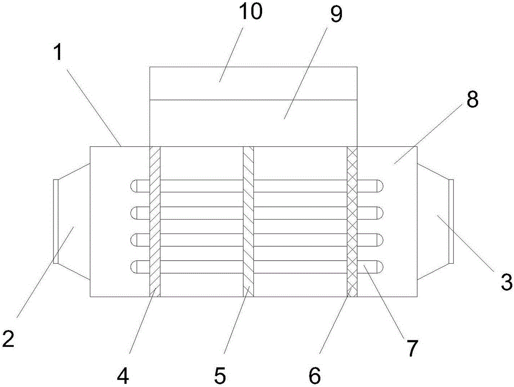
[0015] see figure 1 , in an embodiment of the present invention, an exhaust gas deodorization device based on ultraviolet irradiation, including a microwave generator group 9, a microwave power supply group 10, and a processing shell 1, and an exhaust gas treatment chamber 8 is arranged inside the processing shell 1, and the exhaust gas treatment The processing housing 1 above the chamber 8 is provided with a microwave generator group 9, the microwave generato...


PUM


Abstract

The invention discloses a waste-gas deodorization device based on ultraviolet irradiation. The waste-gas deodorization device comprises a microwave generator set, a microwave power source set and a treating shell. A waste-gas treating cavity is formed inside the treating shell, a gas inlet communicated with the waste-gas treating cavity is formed in the left side of the treating shell, a gas outlet communicated with the waste-gas treating cavity is formed in the right side of the treating shell, a plurality of electrodeless ultraviolet lamp tubes are evenly installed on the inner wall of the waste-gas treating cavity, a first flow intercepting layer, a second flow intercepting layer and a third flow intercepting layer are sequentially arranged in the waste-gas treating cavity from left to right, the first flow intercepting layer is the oxygen carrying material layer, the second flow intercepting layer is the hydrophilic material layer, and the third flow intercepting layer is the oleophylic material layer. The waste-gas deodorization device is simple in structure and good in waste gas treatment effect, the treatment efficiency can be improved for 10 orders of magnitude, device miniaturization is facilitated, and the occupied space of the structure is reduced.

Description

technical field [0001] The invention relates to the technical field of exhaust gas treatment equipment, in particular to an exhaust gas deodorization device based on ultraviolet irradiation. Background technique [0002] The exhaust gas processor with microwave and ultraviolet irradiation is mainly used for the harmless treatment of various low-to-medium concentration volatile organic compounds (VOC5), malodorous gas, oil fume and so on. There are many kinds of organic waste gases, up to tens of thousands, which are seriously harmful to human health. They not only stimulate human eyes, nose, respiratory tract, etc., but also damage organs. The symptoms after poisoning are mostly respiratory system, Digestive system, circulatory system and nervous system and other diseases, and mostly cumulative. Some substances also have carcinogenic effects. In addition, after some organic substances enter the atmosphere, under certain conditions, they will form photochemical smog and cau...

Claims


Application Information

Patent Timeline
Patent Type & Authority Applications(China)
IPC IPC(8): B01D53/74B01D53/76B01D53/44
CPCB01D53/74B01D53/007B01D53/1406B01D53/1487B01D53/1493B01D53/44B01D53/76B01D2251/104B01D2252/40B01D2257/708B01D2259/804B01D2259/806
Inventor 陈天虎秦泽荣王鑫龙张迪迪马欢
Owner 罗光建
Learn More