
Oscillation signal generation circuit

一种生成电路、振荡信号的技术,应用在电脉冲发生器电路、功率振荡器、逻辑电路产生脉冲等方向,能够解决不满足振荡条件、晶体管精度偏差等问题,达到扩宽校准的范围、降低相位噪声的效果

Inactive Publication Date: 2016-10-12
PANASONIC CORP
View PDF4 Cites 6 Cited by
  • Summary
  • Abstract
  • Description
  • Claims
  • Application Information

AI Technical Summary

Problems solved by technology

In particular, VCO (Voltage Controlled Oscillator: Voltage Controlled Oscillator), one of the constituent elements of wireless ICs, is highly likely to fail to satisfy oscillation conditions due to variation in transistor accuracy.

Method used


Image

  • Oscillation signal generation circuit
  • Oscillation signal generation circuit
  • Oscillation signal generation circuit

Examples


Embodiment approach 1

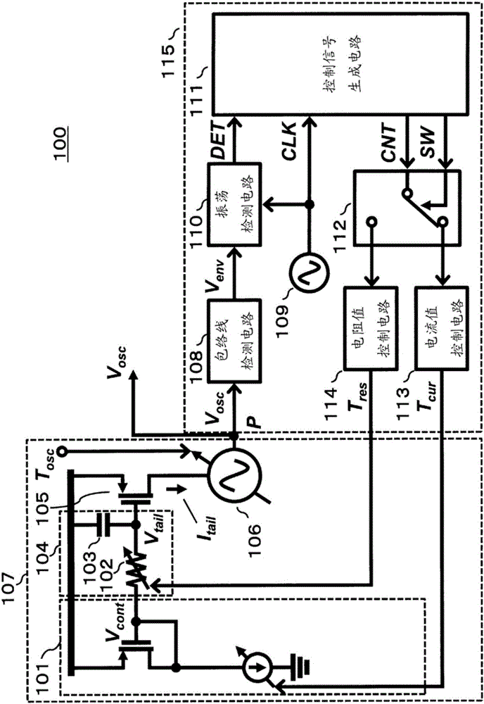
[0055] figure 2 It is a block diagram showing a configuration example of the oscillation signal generation circuit 100 according to Embodiment 1 of the present invention. Such as figure 2 As shown, the oscillation signal generation circuit 100 includes a voltage controlled oscillator 107 and a calibration circuit 115 . The voltage controlled oscillator 107 has: a reference current source circuit 101 ; an RC low-pass filter 104 including a variable resistor 102 and a capacitor 103 ; an end transistor 105 ; and a core circuit 106 . Calibration circuit 115 has: envelope detection circuit 108 ; clock generation circuit 109 ; oscillation detection circuit 110 ; control signal generation circuit 111 ; switch 112 ; current value control circuit 113 ;

[0056] The reference current source circuit 101 has a current source whose current value is variable, based on the current value controlled by the current value control circuit 113, the control voltage V cont Output to RC low pass...

Embodiment approach 2

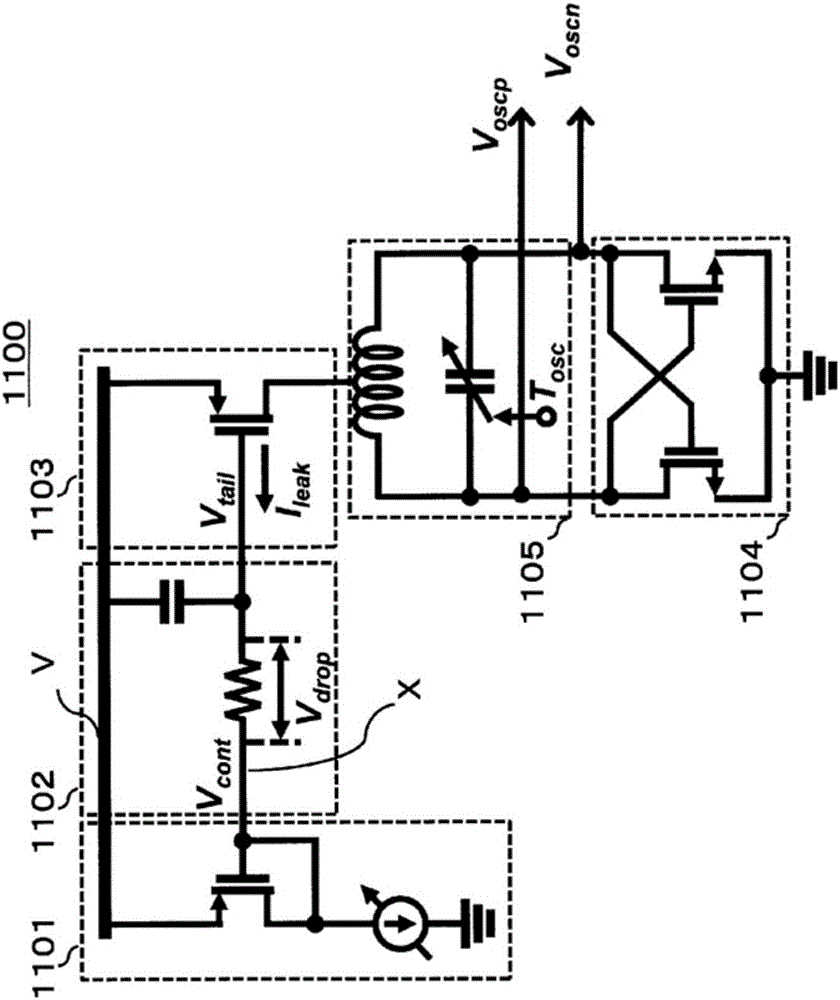
[0176] Generally, the value of the current flowing through the core circuit may cause a change in parasitic capacitance or the like generated in the core circuit. As a result, the output signal from the voltage-controlled oscillation circuit may not oscillate within a desired oscillation frequency range. The oscillation signal generating circuit of the present embodiment is configured to control the output signal to oscillate within a desired oscillation frequency range. A series of loops for confirming and controlling the range of the oscillation frequency in this embodiment is called a frequency range control loop.

[0177] Figure 11 It is a block diagram showing a configuration example of the oscillation signal generating circuit of the present embodiment. again, in Figure 11 in, right with figure 2 common structure, additionally with figure 2 The same reference numerals are used and detailed explanations thereof are omitted.

[0178] Figure 11 The voltage contr...


PUM


Abstract

An oscillation signal generation circuit includes an oscillator and a calibration circuit. The oscillator includes a reference signal source circuit that has a reference signal source outputting a reference signal and converts the output reference signal into a control voltage, a filter that includes a variable resistance and a capacitance and removes noise in the control voltage, a transistor that converts the control voltage which has passed through the filter into a control current and outputs the control current, a core circuit that is driven by the control current and generates an output signal, and an output terminal that outputs the generated output signal. The calibration circuit is connected to the output terminal of the oscillator, detects whether or not the generated output signal is oscillating, and adjusts the current value of the control current by controlling the resistance value of the variable resistance in accordance with the detection result.

Description

technical field [0001] The present invention relates to an oscillation signal generating circuit operating in a high frequency band exceeding 100 GHz. Background technique [0002] In recent years, the frequency has decreased rapidly along with the increase in the number of uses of wireless technologies typified by communication and radar. Therefore, effective use of a frequency band higher than the millimeter wave band, that is, a frequency band exceeding 100 GHz is expected. Therefore, it is expected that a wireless IC (Integrated Circuit; integrated circuit) operating in a frequency band exceeding 100 GHz will spread widely. [0003] In general, wireless ICs are often manufactured using a semiconductor as a material and using a manufacturing method such as a CMOS (Complementary Metal Oxide Semiconductor) process. However, compared with other manufacturing methods, the CMOS process has poor performance at high frequencies, and it is difficult to obtain power gain at high...

Claims


Application Information

Patent Timeline
Patent Type & Authority Applications(China)
IPC IPC(8): H03B5/32
CPCH03B5/32H03K3/027H03B5/1228H03B5/1212H03B2200/0088H03B5/1278H03K5/003H03L7/099H03B5/1209H03B5/24H03L7/00
Inventor 阿部敬之佐藤润二
Owner PANASONIC CORP
Learn More