
Frequency-locked loop calibration of a phase-locked loop gain

Inactive Publication Date: 2011-03-01
QORVO US INC
View PDF10 Cites 35 Cited by
  • Summary
  • Abstract
  • Description
  • Claims
  • Application Information

AI Technical Summary

Benefits of technology

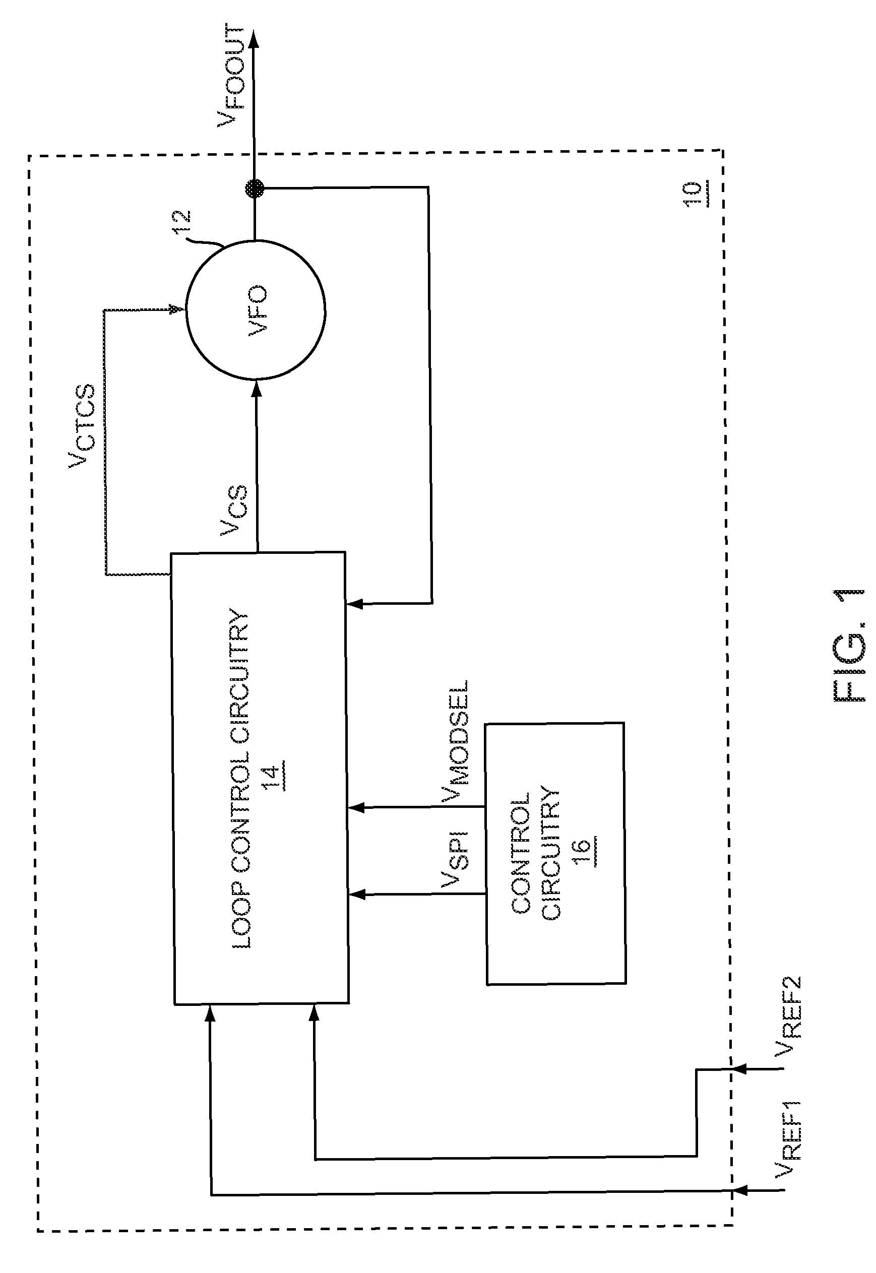
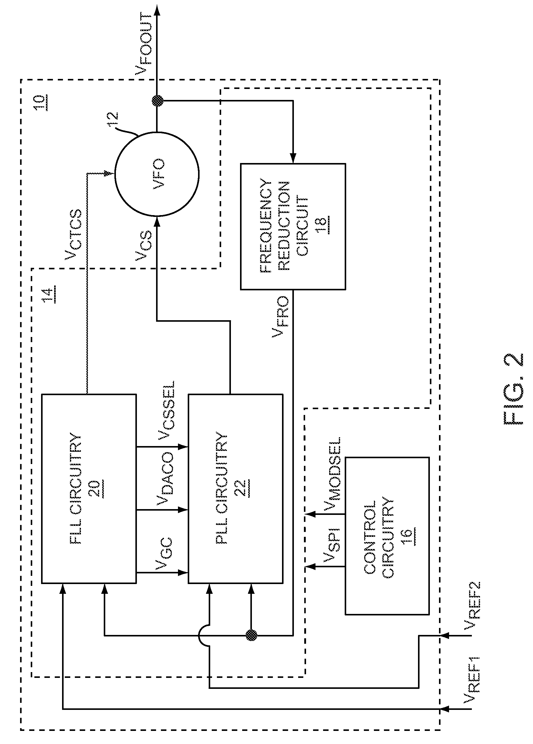
[0005]The present invention relates to a calibrated phase-locked loop (PLL), which has a calibration mode for measuring a tuning gain of a variable frequency oscillator (VFO) and a PLL mode for normal operation. Calibration information based on the tuning gain is used during the PLL mode to regulate a PLL loop gain. During the calibration mode, the calibrated PLL operates as a frequency-locked loop (FLL) for low frequency lock times, and during the PLL mode the calibrated PLL operates as a PLL for high frequency accuracy and low phase noise. By regulating the PLL loop gain, phase lock times during the PLL mode may be reduced.
[0006]In one embodiment of the present invention, the calibration mode may include a first calibration mode and a second calibration mode for measuring the tuning gain of the VFO using two operating points. The calibrated PLL may have a coarse tuning mode. During the coarse tuning mode and the calibration mode, the calibrated PLL operates as an FLL; therefore, some FLL circuit elements may be shared to reduce complexity. The calibrated PLL may have frequency reduction circuitry in a feedback loop of the calibrated PLL to reduce an output frequency of the VFO to a lower feedback frequency to implement an FLL or a PLL. The amount of frequency reduction may be reduced when operating as an FLL, when compared to the amount of frequency reduction used when operating as a PLL, to increase loop gain, which may increase loop bandwidth and reduce frequency lock times. The calibrated PLL may use the calibration information to pre-charge a PLL loop filter before entering the PLL mode to further reduce phase lock times.

Problems solved by technology

Variations in the tuning gain may cause the loop gain of the PLL to vary, leading to undesirable variation in the noise spectrum and dynamic behavior of the PLL.
The time required for tuning gain compensation may comprise a significant portion of the total time allowed for the PLL to settle to the final desired lock frequency, increasing the duty cycle and power consumption of the PLL or in some cases preventing the PLL from meeting the required settle time of some communication systems.
In addition, the prior art calibration techniques may require additional circuitry adding complexity and cost to the PLL.

Method used


Image

  • Frequency-locked loop calibration of a phase-locked loop gain
  • Frequency-locked loop calibration of a phase-locked loop gain
  • Frequency-locked loop calibration of a phase-locked loop gain

Examples


Embodiment Construction

[0005]The present invention relates to a calibrated phase-locked loop (PLL), which has a calibration mode for measuring a tuning gain of a variable frequency oscillator (VFO) and a PLL mode for normal operation. Calibration information based on the tuning gain is used during the PLL mode to regulate a PLL loop gain. During the calibration mode, the calibrated PLL operates as a frequency-locked loop (FLL) for low frequency lock times, and during the PLL mode the calibrated PLL operates as a PLL for high frequency accuracy and low phase noise. By regulating the PLL loop gain, phase lock times during the PLL mode may be reduced.

[0006]In one embodiment of the present invention, the calibration mode may include a first calibration mode and a second calibration mode for measuring the tuning gain of the VFO using two operating points. The calibrated PLL may have a coarse tuning mode. During the coarse tuning mode and the calibration mode, the calibrated PLL operates as an FLL; therefore, s...


PUM


Abstract

The present invention relates to a calibrated phase-locked loop (PLL), which has a calibration mode for measuring a tuning gain of a variable frequency oscillator (VFO) and a PLL mode for normal operation. Calibration information based on the tuning gain is used during the PLL mode to regulate a PLL loop gain. During the calibration mode, the calibrated PLL operates as a frequency-locked loop (FLL) for low frequency lock times, and during the PLL mode the calibrated PLL operates as a PLL for high frequency accuracy and low noise. By regulating the PLL loop gain, the desired noise spectrum and dynamic behavior of the PLL may be maintained in spite of variations in the operating characteristics or in the characteristics of the PLL components.

Description

[0001]This application claims the benefit of provisional patent application Ser. No. 61 / 015,751, filed Dec. 21, 2007, the disclosure of which is hereby incorporated herein by reference in its entirety.FIELD OF THE INVENTION[0002]Embodiments of the present invention relate to phase-locked loops (PLLs) and frequency-locked loops (FLLs), both of which may be used in frequency synthesizers that may be used in wireless communications systems.BACKGROUND OF THE INVENTION[0003]Conventional frequency synthesizers generally include a phase-locked loop (PLL). A PLL is a device that generates an output frequency that is a function of a reference frequency. When implemented in a device such as a wireless transceiver, the output frequency of the PLL may change frequently. For example, the output frequency of the PLL changes at start-up and when changing channels. In each of these situations, it is desirable for the PLL to settle as quickly as possible on a desired output frequency. Further, in fr...

Claims


Application Information

Patent Timeline
IPC IPC(8): H03L7/00
CPCH03L7/087H03L7/0891H03L7/093H03L7/099H03L7/113H03L7/1974H03L2207/06H03L2207/12
Inventor JANESCH, STEPHEN T.
Owner QORVO US INC
Learn More