
Process and device for generating electricity by using LNG cold energy

A process and cold energy technology, which is applied in the field of processes and devices using LNG cold energy for power generation, can solve the problems of large temperature difference of cold energy recovery heat exchanger, large loss of effective energy, complicated process, etc., so as to reduce the loss of effective energy and easily The effect of starting and stopping, and the process is simple

Active Publication Date: 2016-05-11
XINDI ENERGY ENG TECH
View PDF9 Cites 7 Cited by
  • Summary
  • Abstract
  • Description
  • Claims
  • Application Information

AI Technical Summary

Problems solved by technology

This system only uses one kind of working fluid and only one-stage circulation. The problem is that the temperature difference of the cold energy recovery heat exchanger is relatively large, and the loss of effective energy will be relatively large.
The process published by this patent application is basically the same as the process published by CN103075250A. Although the cooling capacity of LNG can be recovered from the entire temperature difference of -160°C to 0°C, the process is too complicated and there are many moving equipment, which is suitable for the requirement of cold energy utilization efficiency. higher occasions

Method used


Image

  • Process and device for generating electricity by using LNG cold energy

Examples


Embodiment 1

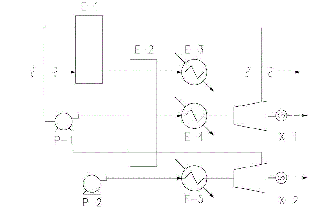
[0028] Such as figure 1 As shown, the LNG boosted by the LNG booster pump (about -160°C ~ -140°C) is reheated and vaporized by the LNG evaporator E-1, and then continues to recover cooling capacity through the LNG heating heat exchanger E-2 , and finally heated by one or more natural gas heat exchangers E-3 to a temperature suitable for sending to the downstream pipeline network (at least 5°C lower than the ambient temperature), and then enters the pipeline network. The cold energy released in this process is recycled to generate electricity through two separate cycles, Cycle 1 and Cycle 2.

[0029]Cycle 1: 5.6 barg, -53.9°C ethylene passes through the LNG evaporator E-1, exchanges heat with the pressurized LNG to take away the cooling capacity, the ethylene in cycle 1 is cooled to about -70°C and liquefied, and then is The ethylene booster pump P-1 is boosted to 23.5 barg. The pressurized ethylene enters the LNG heating heat exchanger E-2, and exchanges heat with the propan...

Embodiment 2

[0033] Such as figure 1 As shown, the LNG boosted by the LNG booster pump (about -160°C ~ -140°C) is reheated and vaporized by the LNG evaporator E-1, and then continues to recover the cooling capacity through the LNG heating heat exchanger, and finally passes through the One or more natural gas heat exchangers E-3 are heated to a temperature suitable for feeding into the downstream pipeline network (at least 5°C lower than the ambient temperature) and enter the pipeline network. The cold energy released in this process is recycled to generate electricity through two separate cycles, Cycle 1 and Cycle 2.

[0034] Cycle 1: 5.6 barg, -53.9°C ethylene passes through the LNG evaporator E-1, exchanges heat with the pressurized LNG to take away the cooling capacity, the ethylene in cycle 1 is cooled to about -90°C and liquefied, and then is The ethylene booster pump P-1 is boosted to 23.5 barg. The pressurized ethylene enters the LNG heating heat exchanger E-2, and exchanges heat ...


PUM


Abstract

The invention relates to a process and device for generating electricity by using LNG cold energy. A lot of cold energy is released in the process of supplying vaporized LNG to a downstream pipe network; and the process uses two independent cycles to recover the cold energy for generating electricity, so that the loss of the cold energy is prevented, the economic benefit of enterprises is promoted, the pollution problem caused by power generation of a power plant is prevented in power generation, and the requirements of energy conservation and environmental protection are accorded with.

Description

technical field [0001] The invention relates to a process for generating electricity by recycling cold energy of LNG, in particular to a process for generating electricity by recycling LNG cold energy in a two-stage cold recovery cycle. Background technique [0002] LNG carries a large amount of low-temperature cold energy. As my country imports a large amount of LNG, its economic value can no longer be ignored. Cold energy can be utilized by direct or indirect methods. LNG direct utilization methods include cold energy power generation, seawater desalination, liquefaction and separation of air (liquid oxygen, liquid nitrogen), light hydrocarbon separation, frozen warehouses, liquefaction of carbonic acid, dry ice production, air conditioning, etc.; indirect utilization includes frozen food, low-temperature crushing of waste Processing, cryopreservation, cryogenic medical treatment, food preservation, etc. The efficiency of the existing cold energy power generation process...

Claims


Application Information

Patent Timeline
Patent Type & Authority Applications(China)
IPC IPC(8): F01K23/00F01K25/10
CPCF01K23/00F01K25/10
Inventor 何振勇张生郑忠英牛卓韬张洪耀傅建青王培寇伟伟
Owner XINDI ENERGY ENG TECH
Learn More