Eureka AIR delivers breakthrough ideas for toughest innovation challenges, trusted by R&D personnel around the world.

A system and method for producing hydrogen-rich gas and liquid methane

A technology of liquid methane and hydrogen-rich gas, which is applied in refrigeration and liquefaction, liquefaction, hydrogen separation, etc., can solve the problems of waste and consumption, and achieve the effects of saving power consumption, good rectification effect, and reducing circulation volume

Inactive Publication Date: 2017-06-27
KAIFENG AIR SEPARATION GROUP
View PDF2 Cites 0 Cited by
  • Summary
  • Abstract
  • Description
  • Claims
  • Application Information

AI Technical Summary

Problems solved by technology

[0005] The Chinese patent with the application number 201320852728.8 and the name of the device for producing liquefied natural gas and hydrogen-rich products from methane-rich gas, although the application number is 201210065876.5 and the name is the process of dehydrogenating nitrogen from methane-rich gas and producing liquefied natural gas. The Chinese patent and application number of the device is 210010291609.5, and the Chinese patent titled the process of dehydrogenation, nitrogen, carbon monoxide from methane-rich gas and producing liquefied natural gas has some improvement in refrigeration effect, but at the cost of consuming external frozen water, The chilled water is made by cooling the lithium bromide air conditioner, and the lithium bromide air conditioner still needs to consume a part of steam, so it causes certain limitations to the use and causes a kind of waste

Method used


Image

  • A system and method for producing hydrogen-rich gas and liquid methane

Examples


Embodiment 1

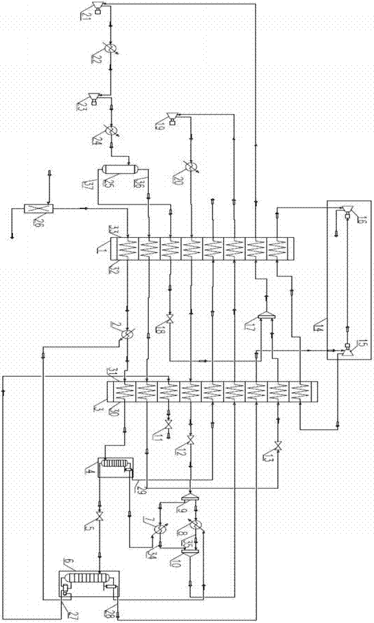
[0028] Such as figure 1 As shown, a system for producing hydrogen-rich gas and liquid methane mainly includes a purge gas purification unit and a low-temperature liquefaction separation unit. The low-temperature liquefaction separation unit includes a liquefaction cold box system, a mixed refrigerant cycle compression system and a nitrogen cycle compression system; the liquefaction cold box system includes a first plate-fin heat exchanger 1, a second plate-fin heat exchanger Device 3, high-pressure rectification tower 4, low-pressure rectification tower 6, and exhaust gas expander 14; Described high-pressure rectification tower 4 tower tops are provided with first condenser 7, and described low-pressure rectification tower 6 tower bottoms are provided with There is an evaporator 2, and the top of the tower is provided with a second condenser 8; the mixed refrigerant cycle compression system includes a primary mixed refrigerant compressor 21, a primary cooler 22, a secondary mi...

Embodiment 2

[0035] A method for producing hydrogen-rich gas and liquid methane. The synthetic ammonia or methanol purge gas with a pressure of 1.6MPa~7.0MPa passes through the purification unit 26, and the trace amount of CO in the purge gas is absorbed by the adsorbent in the purification unit. 2 and water are removed, and the relaxed gas after removing impurities enters the first plate-fin heat exchanger 1 and is cooled to 145K~165K, and enters the low-pressure rectification tower evaporator 2 as a heat source to be further cooled, and the temperature after cooling is 135K ~ 155K, enter the second plate-fin heat exchanger 3 and cool to 110K ~ 117K, the gas after cooling enters the high-pressure rectification tower 4 for rectification separation, and the purity obtained at the top of the high-pressure rectification tower is 91.4 %mol of hydrogen enters the cold end 30 of the second plate-fin heat exchanger and the cold end 32 of the first plate-fin heat exchanger to reflow and reheat to o...


PUM


Abstract

The invention relates to a system and method for producing hydrogen-rich gas and liquid methane. The system mainly includes a purge gas purification unit and a cryogenic liquefaction separation unit. The invention adopts mixed refrigerant compression cycle refrigeration, nitrogen cycle compression refrigeration and waste gas expansion refrigeration, and the synthetic ammonia or methanol purge gas is rectified and separated in a high-efficiency rectification tower to obtain hydrogen-rich gas and liquid methane. The process is simple, the energy consumption is low, and the recovery rate is high. high. The invention provides a system and method for producing hydrogen-rich gas and liquid methane with good reliability, low operating cost and high product purity.

Description

technical field [0001] The invention relates to the field of gas separation, in particular to a system and method for producing hydrogen-rich gas and liquid methane from synthetic ammonia or methanol purge gas. Background technique [0002] Ammonia or methanol is one of the important raw materials of basic organic chemical industry. The synthesis of ammonia or methanol mainly uses coal or natural gas as raw material. After a certain transformation, synthesis gas is obtained. In my country, ammonia synthesis or methanol production enterprises mainly use coal as raw material. In addition to producing effective components CO and H in the process 2 In addition, CH 4 and N 2 and other invalid gases. As the reaction proceeds, a large number of invalid components accumulate to affect the conversion rate of the reaction. The invalid components need to be discharged from the device to produce a large amount of synthetic ammonia or methanol purge gas. The main components of purge gas...

Claims


Application Information

Patent Timeline
Patent Type & Authority Patents(China)
IPC IPC(8): F25J3/02F25J5/00C07C9/04C01B3/50
CPCF25J2215/04F25J3/0233F25J3/0252F25J2270/18F25J2270/66F25J2270/04F25J2200/74F25J2290/34F25J2270/12F25J2270/42F25J2210/20F25J2210/12F25J2200/40F25J3/0219
Inventor 韦向攀王剑峰卓跃光孙宇
Owner KAIFENG AIR SEPARATION GROUP
Why Eureka
Eureka Blog
Learn More