Distributed fiber sound wave detection apparatus and method based on wave beam formation
A distributed optical fiber and sound wave detection technology, which is applied in measuring devices, measuring ultrasonic/sonic waves/infrasonic waves, using wave/particle radiation, etc., can solve the problems of difficult reliable operation of electronic sensors, achieve small size, improve flexibility, and expand effect of scale
- Summary
- Abstract
- Description
- Claims
- Application Information
AI Technical Summary
Problems solved by technology
Method used
Image

Examples
Embodiment 1
[0028] Embodiment 1: Distributed optical fiber acoustic wave detection device based on beamforming
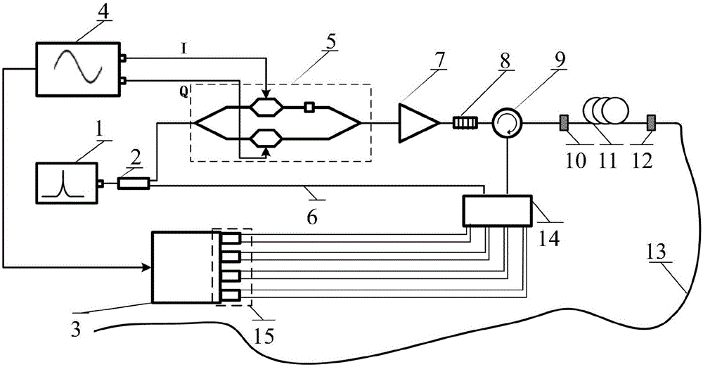
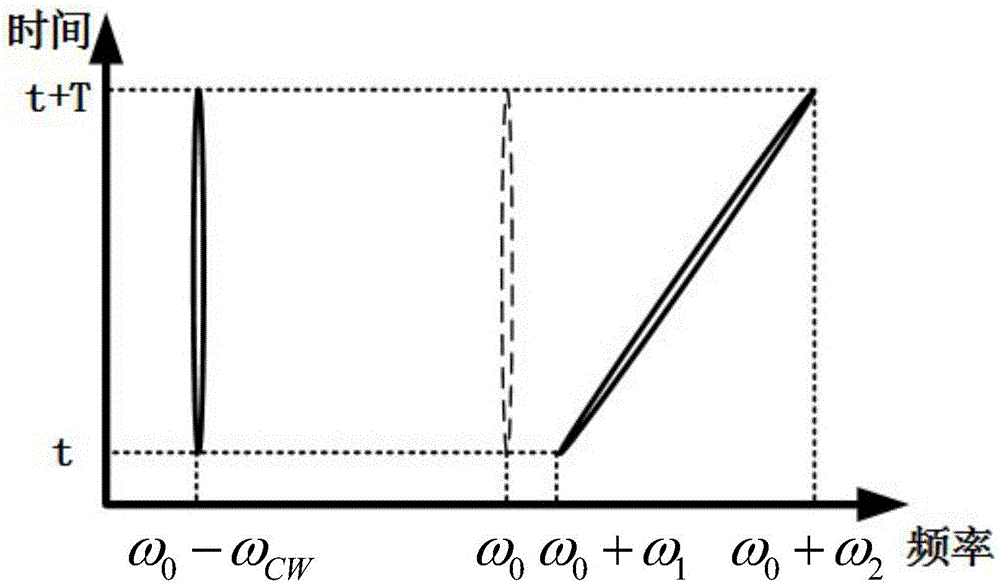
[0029] Such as figure 1 As shown, the light source 1 emits frequency ω 0The continuous laser light passes through the 1x2 coupler 2, and is divided into two paths of local reference light and signal light: the local reference light passes through the reference arm light 6, and reaches the 90° optical mixer 14; The parallel Mach-Zehnder electro-optic modulator 5 is modulated to simultaneously contain the frequency ω 0 -ω CW fixed frequency components and frequency ω 0 Pulse signal light with +ω(t) linear frequency sweep component (such as figure 2 shown); the pulse signal light is amplified successively through the erbium-doped fiber amplifier 7, filtered by the optical filter 8 and unidirectionally transmitted by the circulator 9, and then injected into the reference length optical fiber 11 and the sensing optical fiber 13 specially arranged, and the pulse After the signa...
Embodiment 2
[0045] Embodiment 2: Distributed optical fiber acoustic wave detection method based on beamforming
[0046] Such as figure 1 As shown, the light source 1 emits frequency ω 0 The continuous laser light passes through the 1x2 coupler 2 and is divided into two paths of local reference light and signal light; the local reference light passes through the reference arm 6 and reaches the 90° optical mixer 14; the signal light passes through the two-way parallel light controlled by the arbitrary waveform generator Mach-Zehnder electro-optic modulator 5, is modulated as figure 2 The shown double sideband heterogeneous optical pulse, the lower sideband is fixed frequency ω 0 -ω CW , the upper sideband frequency is ω 0 +ω(t); the pulse signal light is amplified by the erbium-doped fiber amplifier 7, the optical filter 8 and the circulator 9 successively, and then injected into the sensing fiber, and the pulse signal light is scattered back Rayleigh in the passing optical fiber 13 R...
Embodiment 3
[0048] Embodiment 3: application example
[0049] In construction sites and mountainous road areas where slope stability monitoring is required, the distributed optical fiber acoustic wave detection device based on beamforming of the present invention is used to monitor characteristic low-frequency sound waves and locate the sound source, so as to detect impending accidents near the sound source in advance Make predictions and alerts. Bury the sensing fiber 13 in the area that needs to be monitored, and the arrangement includes a one-dimensional linear sensing fiber 20, a two-dimensional square sensing fiber 21, and a three-dimensional conical sensing fiber 22. The fiber optic acoustic wave detection method is used to extract the acoustic signal.
PUM
| Property | Measurement | Unit |
|---|---|---|
| Length | aaaaa | aaaaa |
Abstract
Description
Claims
Application Information
 - R&D
- Intellectual Property
- Life Sciences
- Materials
- Tech Scout
- Unparalleled Data Quality
- Higher Quality Content
- 60% Fewer Hallucinations
Browse by: Latest US Patents, China's latest patents, Technical Efficacy Thesaurus, Application Domain, Technology Topic, Popular Technical Reports.
© 2025 PatSnap. All rights reserved.Legal|Privacy policy|Modern Slavery Act Transparency Statement|Sitemap|About US| Contact US: help@patsnap.com