
Micro fluidic electro-spray chip device and manufacture method

An electrospray and microfluidic technology, applied in electrical components, electrode system manufacturing, discharge tube/lamp manufacturing, etc., to improve repeatability, stability and reliability, facilitate manufacturing, and overcome non-uniformity problems.

Inactive Publication Date: 2015-11-11
杨金金
View PDF15 Cites 12 Cited by
  • Summary
  • Abstract
  • Description
  • Claims
  • Application Information

AI Technical Summary

Problems solved by technology

[0005] Aiming at the defects existing in the existing electrospray chip device, the present invention provides a microfluidic electrospray chip device and a manufacturing method, which provides a more uniform auxiliary airflow close to the electrospray needle, and uses a unique electrode structure to ensure The electrospray uniformity of the needle device overcomes the problem of inhomogeneity, and the manufacturing method conveniently realizes the manufacture of the electrospray chip device

Method used


Image

  • Micro fluidic electro-spray chip device and manufacture method
  • Micro fluidic electro-spray chip device and manufacture method
  • Micro fluidic electro-spray chip device and manufacture method

Examples


Embodiment Construction

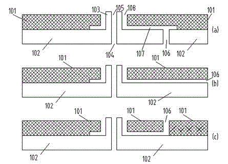
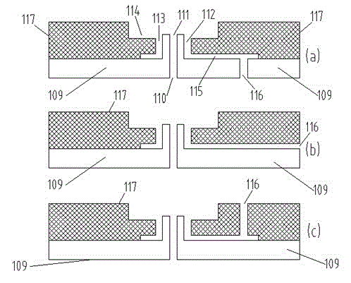
[0036] The structure of a specific embodiment of the present invention is as figure 1 As shown in (a), the liquid chip 102 has two substantially parallel surfaces, one is the liquid inlet surface and the other is the liquid outlet surface; there is at least one liquid inlet hole 104 on the liquid inlet surface for the liquid to flow in; the liquid outlet surface has at least An outlet hole 105 allows liquid to flow out; the inlet hole 104 and the outlet hole 105 are in fluid communication. On the liquid outlet surface, a region around the liquid outlet hole 105 is etched to a depth perpendicular to the liquid chip 102, so that a tubular electrospray nozzle 103 is formed at the liquid outlet hole 105; the gas chip 101 has two substantially parallel Two surfaces, one is the air inlet surface, and the other is the air outlet surface; there is at least one air outlet perforation 108 between the air inlet surface and the air outlet surface; there are etched grooves 107 on the air i...


PUM


Abstract

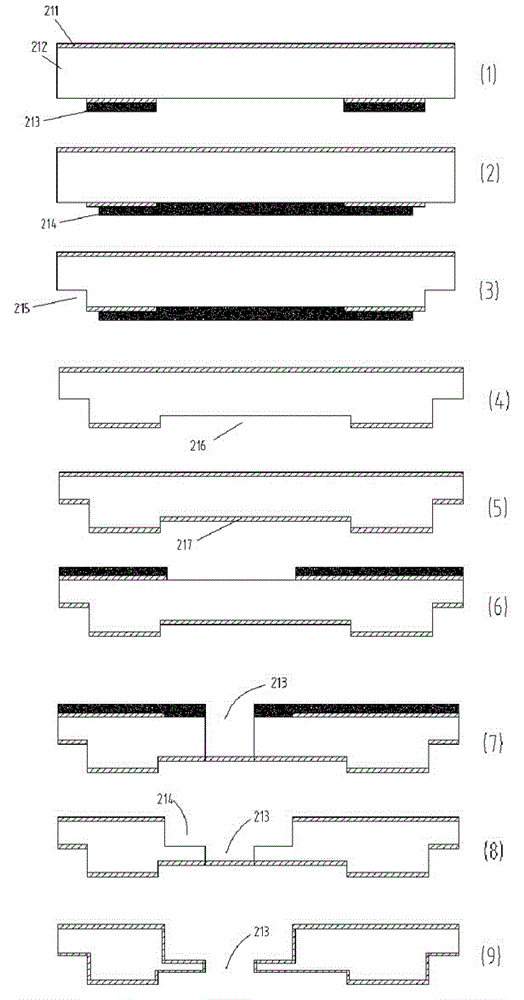
The invention relates to an electro-spray device, and especially to a micro fluidic electro-spray chip device and a manufacture method. The chip device provides more uniform auxiliary airflow close to an electro-spray pin, a unique electrode structure ensures the electro-spray uniformity of the pin, and the problem of non-uniformity is overcome. The manufacture method can be used to conveniently manufacture the electro-spray chip device. The micro fluidic electro-spray chip device comprises fluid chips and gas chips, each fluid chip comprises a fluid transmission channel and the electro-spray pin, each gas chip comprises a gas transmission groove and a second electrode structure, and the fluid chip is bonded with the gas chip to form the micro fluidic electro-spray chip device. The manufacture method comprises the following steps that the gas chips and the fluid chips are processed, and the side, with the groove, of the gas chip is bonded with the side, with the electro-spray pin, of the fluid chip to form the micro fluidic electro-spray chip device, and during bonding, accurate alignment is realized by aligning marks on a silicon chip, so that the electro-spray pin on the fluid chip can be nested into a through hole of the gas chip.

Description

technical field [0001] The present invention relates to an electrospray device, especially an electrospray device used as an ion source for a mass spectrometer; the device of the present invention relates to microfluidic chip technology or microfluidic chip technology; the manufacturing technology of the device of the present invention relates to micromachining technology, microelectronics The invention relates to a micromachining technology, specifically a microfluidic electrospray chip device and a manufacturing method thereof. Background technique [0002] Electrospray is usually a liquid that forms a Taylor cone at the nozzle of a tubular nozzle under the action of a strong electric field, and the tip of the cone ejects tiny charged droplets. As a main ion source, electrospray technology is widely used in mass spectrometry, and is an important part of liquid chromatography-mass spectrometry analysis technology. It plays a key role in the analysis and research of biologic...

Claims


Application Information

Patent Timeline
Patent Type & Authority Applications(China)
IPC IPC(8): H01J49/16H01J9/00
Inventor 李杰
Owner 杨金金
Learn More