
EFI (exploding foil initiator) chip unit, preparation method of EFI chip unit, and exploding foil initiation device based on chip unit

A chip unit and detonation device technology, which is applied in blasting barrels, offensive equipment, weapon accessories, etc., can solve the problems of being unable to withstand high overload, large volume of detonation device, complex process, etc., and achieve low cost, small size, and reduced process flow Effect

Inactive Publication Date: 2015-06-10
NANJING UNIV OF SCI & TECH
View PDF4 Cites 21 Cited by
  • Summary
  • Abstract
  • Description
  • Claims
  • Application Information

AI Technical Summary

Problems solved by technology

So far, Parylene has been reported as the insulating layer of the one-shot switch and the flyer of the detonating foil detonator, but there is no report that Parylene is used in the one-time molding of the one-shot switch and the detonating foil integrated chip, so the overall volume of the detonating device is large. Moreover, the process is complex, the cost is high, and it cannot withstand complex environments such as high overload

Method used


Image

  • EFI (exploding foil initiator) chip unit, preparation method of EFI chip unit, and exploding foil initiation device based on chip unit
  • EFI (exploding foil initiator) chip unit, preparation method of EFI chip unit, and exploding foil initiation device based on chip unit
  • EFI (exploding foil initiator) chip unit, preparation method of EFI chip unit, and exploding foil initiation device based on chip unit

Examples


preparation example Construction

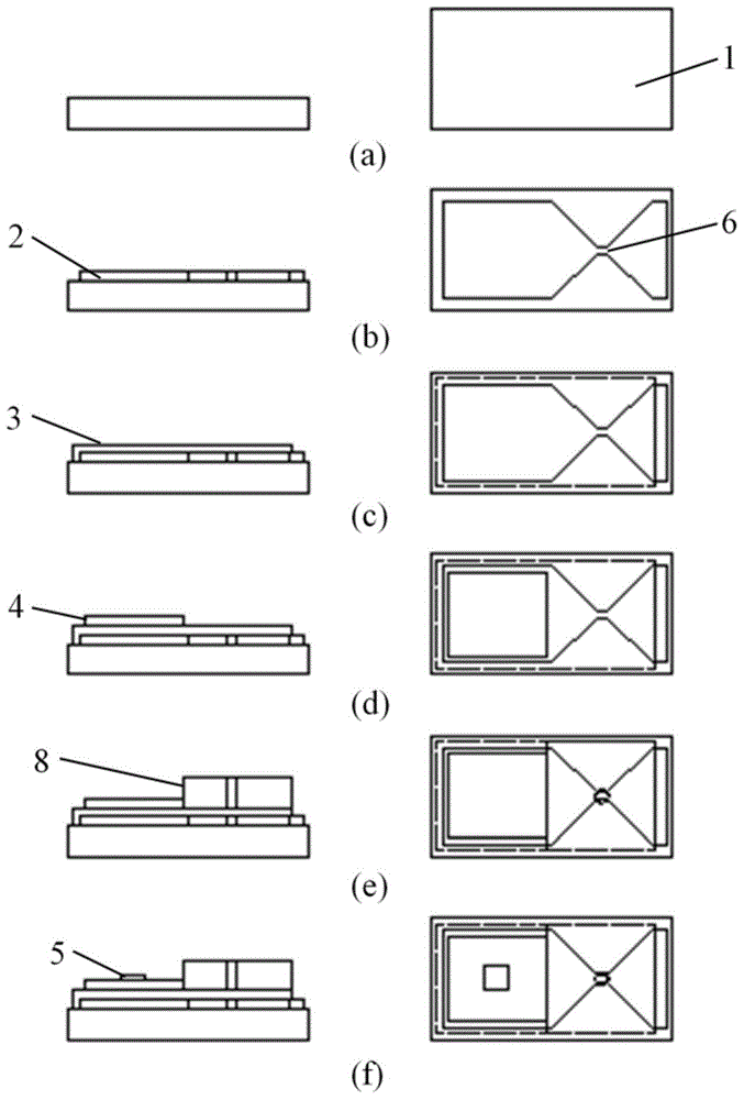
[0024] combine image 3 , the preparation method of EFI chip unit of the present invention, comprises the following steps:

[0025] In the first step, the surface of the ceramic substrate 1 is cleaned, and a Ti layer and a Cu layer are deposited on the surface of the silicon-based substrate by using a photolithographic stripping process and a magnetron sputtering process to form a metal Ti / Cu layer 2, and the metal Ti / Cu Layer 2 is divided into a lower electrode area and a bridge foil area. The lower electrode area is a rectangular structure, and the bridge foil area is a bridge-shaped structure with two ends wide and the middle narrow. The bridge foil area gradually becomes narrow from the wide ends on both sides to the middle Part of the explosion foil 6, wherein one wide end is connected with the lower electrode area;

[0026] In the second step, Chemask is used to protect the wide end of the bridge foil region that is not connected to the lower electrode region, the rest ...

Embodiment 1

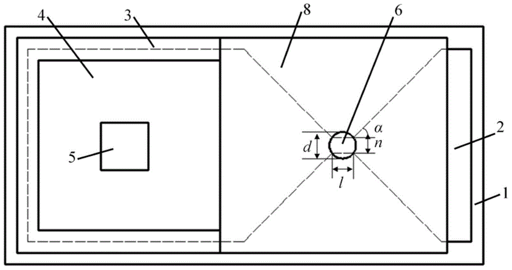
[0036] This embodiment integrates the EFI chip unit of the one-shot switch and the acceleration chamber, and the unit includes a ceramic substrate 1, a metal Ti / Cu layer 2, a Parylene C layer 3, an upper electrode Ti / W / Ti / Cu / Au4, a Schottky Second tube 5, Su8 acceleration chamber; metal Ti / Cu layer 2 is set on the ceramic substrate 1, and the metal Ti / Cu layer 2 is divided into a lower electrode area and a bridge foil area, and the lower electrode area has a rectangular structure, The bridge foil area is a bridge-shaped structure with two ends wide and the middle narrow. The narrow part is the explosive foil 6, and the wide end is connected to the lower electrode area. The length l of the explosive foil 6 bridge-shaped area is 0.3mm, and the width n is 0.3mm. A Parylene C layer 3 is arranged on the metal Ti / Cu layer 2, and the Parylene C layer 3 completely covers the lower electrode area and part of the bridge foil area, so that the metal copper layer at one end of the bridge f...


PUM


Abstract

The invention discloses an EFI (exploding foil initiator) chip unit, a preparation method of the EFI chip unit, and an exploding foil initiation device based on the chip unit. The EFI chip unit comprises a ceramic substrate, a metal Ti / Cu layer, a Parylene C layer, an upper electrode Ti / W / Ti / Cu / Au, a Schottky diode and an Su8 acceleration chamber. The exploding foil initiation device comprises the EFI chip unit, a flying plate, an explosive cylinder, a printed circuit board base, a transmission line, a low-voltage chip capacitor and a high-voltage chip capacitor. The metal Ti / Cu layer serves as a lower electrode in a one-shot switch unit and as an exploding foil in an exploding foil initiation unit; the Parylene C layer serves as an insulation layer between the upper electrode and the lower electrode in the one-shot switch unit and as a flying plate layer of an exploding foil initiator in the exploding foil initiation unit; the acceleration chamber employs integrated manufacturing of Su8 photoresist; the technical process is reduced; the cost is low; the size is small; and the Schottky diode has a reverse breakdown characteristic, so that a switch can resist stray current and has intrinsic safety.

Description

technical field [0001] The invention relates to the technical field of low-energy miniature ignition and detonation devices, in particular to an EFI chip unit, a preparation method thereof, and an explosive foil detonation device based on the chip unit. Background technique [0002] The Exploding Foil Initiator system (EFIs), also known as the In-line Safe and Arming Apparatus, consists of two parts: a pulse power unit and an exploding foil initiation unit. The pulse power unit provides electrical energy for the detonating foil detonating unit, including transformers, high-voltage energy storage capacitors, high-voltage switches and control circuits, etc. Explosive foil detonating unit is also called shock plate detonator, which mainly includes metal bridge foil, flyer layer, accelerating chamber and insensitive charge. Because it does not contain sensitive energy-containing units, it has the advantages of strong anti-electromagnetic interference and impact resistance, and ...

Claims


Application Information

Patent Timeline
Patent Type & Authority Applications(China)
IPC IPC(8): F42B3/13
Inventor 朱朋胡博沈瑞琪叶迎华吴立志胡艳
Owner NANJING UNIV OF SCI & TECH
Learn More