Novel combined bio-floating bed
A biological floating bed and combined technology, applied in the field of biological floating bed, can solve the problems of poor applicability and limited absorption capacity of plant roots, and achieve the effects of being difficult to move, reducing water disturbance and high surface energy.
- Summary
- Abstract
- Description
- Claims
- Application Information
AI Technical Summary
Problems solved by technology
Method used
Image
Examples
Embodiment 1
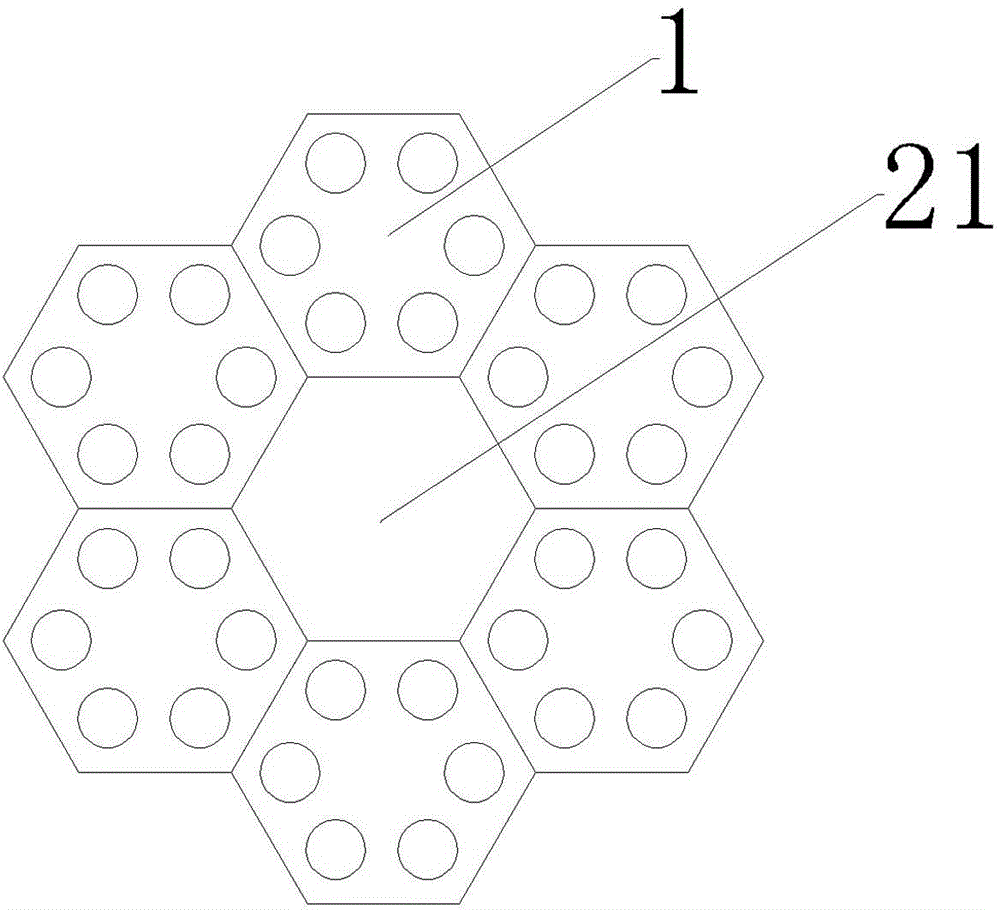
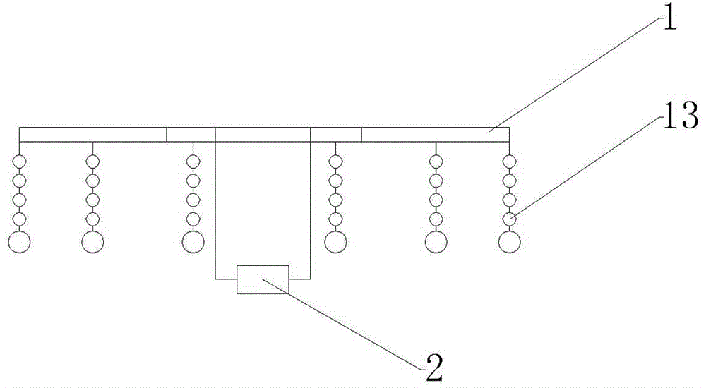
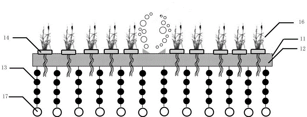
[0034] Such as Figure 1~4 As shown, the combined biological floating bed of this embodiment includes several floating bed monomers 1 and aeration devices 2; the six regular hexagonal floating bed monomers 1 are connected along the horizontal plane to form a first space configuration, and the first space The configuration is a positive six-petal flower configuration with an aeration chamber 21 inside; the aeration device 2 is arranged in the aeration chamber 21 and is 0.5-1m away from the bottom of the floating bed frame 11. The floating bed monomer 1 includes a floating bed frame 11, a floating bed body 12 arranged inside the floating bed frame 11, and a biofilm carrier filler 13 arranged below the floating bed body 12; the floating bed body 12 is provided with planting grooves 14.
[0035]The adjacent floating bed frames 11 are connected by connecting ropes to form a whole, and the floating bed frames 11 are fixed with rivets to fix the floating bed body 12 . The frame bod...
Embodiment 2
[0044] Such as Figure 5 As shown, the combined biological floating bed of this embodiment is a bed body formed by connecting several floating bed monomers 1 and an aeration chamber 21 arranged inside the bed body, and an aeration device 2 is arranged inside the aeration chamber 21 . The bed body is in the shape of a positive four-petal flower with an aeration chamber 21 inside; the aeration device 2 is arranged in the aeration chamber 21 and is 0.5-1m away from the bottom of the floating bed frame 11 . The floating bed monomer 1 includes a floating bed frame 11, a floating bed body 12 arranged inside the floating bed frame 11, and a biofilm carrier filler 13 arranged below the floating bed body 12; the floating bed body 12 is provided with planting grooves 14.
[0045] The adjacent floating bed frames 11 are connected by connecting ropes to form a whole, and the floating bed frames 11 are fixed with rivets to fix the floating bed body 12 . The frame body 11 of the floating...
Embodiment 3
[0049] Such as Figure 6 As shown, the combined biological floating bed of this embodiment includes several floating bed monomers 1 and aeration devices 2; the three rectangular floating bed monomers 1 are connected along the horizontal plane to form a first space configuration, and the first space The configuration is a triangular configuration with an aeration chamber 21 inside; the aeration device 2 is arranged in the aeration chamber 21 and is 0.5-1m away from the bottom of the floating bed frame 11 . The floating bed monomer 1 includes a floating bed frame 11, a floating bed body 12 arranged inside the floating bed frame 11, and a biofilm carrier filler 13 arranged below the floating bed body 12; the floating bed body 12 is provided with planting grooves 14.
[0050] The adjacent floating bed frames 11 are connected by connecting ropes to form a whole, and the floating bed frames 11 are fixed with rivets to fix the floating bed body 12 . The frame body 11 of the floatin...
PUM
 Abstract
Description
Claims
Application Information
 - R&D
- Intellectual Property
- Life Sciences
- Materials
- Tech Scout
- Unparalleled Data Quality
- Higher Quality Content
- 60% Fewer Hallucinations
Browse by: Latest US Patents, China's latest patents, Technical Efficacy Thesaurus, Application Domain, Technology Topic, Popular Technical Reports.
© 2025 PatSnap. All rights reserved.Legal|Privacy policy|Modern Slavery Act Transparency Statement|Sitemap|About US| Contact US: help@patsnap.com


