Rock-soil body temperature-control dynamic characteristic test system and test method
A technology of dynamic characteristics and test system, applied in strength characteristics, using stable tension/pressure to test material strength, measuring devices, etc., can solve the problems of reduced viscosity, long time required for test temperature, and resistance of various components of the instrument. High temperature requirements and other issues, to achieve the effect of easy loading and unloading
- Summary
- Abstract
- Description
- Claims
- Application Information
AI Technical Summary
Problems solved by technology
Method used
Image
Examples
Embodiment 1
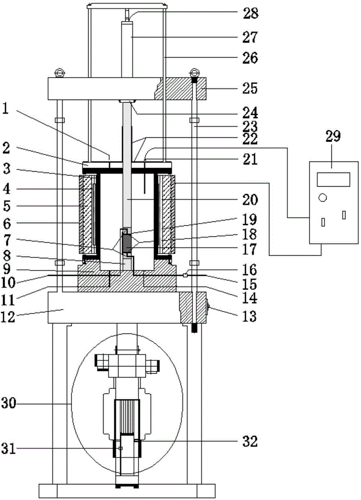
[0038] A rock and soil temperature control dynamic characteristic test system, such as figure 1 and figure 2 As shown, it includes a dynamic triaxial pressure chamber and a temperature control device. The dynamic triaxial pressure chamber includes a pressure chamber cylinder 3. The upper end opening of the pressure chamber cylinder 3 is sealed with a pressure chamber upper cover 2. The pressure chamber cylinder 3 The bottom is provided with a chassis 9, and the center of the bottom of the pressure chamber cylinder 3 is longitudinally provided with a piston rod 8. The upper end of the pressure chamber cylinder 3 is located above the piston rod 8 and is longitudinally provided with an uploading force rod 20. The lower end of the uploading force rod 20 is connected to the piston A sample 17 is placed between the upper ends of the rods 8, a loading frame cap 12 is provided at the bottom of the chassis 9, a loading frame beam 25 is provided directly above the upper cover 2 of the ...
Embodiment 2
[0058] A method for testing the dynamic characteristics of rock and soil temperature control, mainly used to measure the dynamic parameters of rock and soil at different temperatures of soil samples, including a pore pressure sensor 16, a temperature sensor 21, a pressure sensor 24, an axial displacement sensor 31, Deformation sensor 32, confining pressure sensor 33 and lateral displacement sensor 34, the specific structure of its test system is as described in the above-mentioned embodiment 1 and as figure 1 and figure 2 As shown, the specific steps of the method are as follows:
[0059] (1) Sample installation
[0060] After the soil sample 17 is saturated with water head, vacuum pumping or counter pressure, stick 6-7 filter paper strips on the side of the sample 17, and stick filter paper sheets and permeable stones 20 on both ends in turn. 17 is coated with latex film 19, and then the sample 17 is placed on the piston rod 8 in the pressure chamber cylinder 3, and the ma...
Embodiment 3
[0082] Using the temperature-controlled dynamic triaxial test system of Example 1, select a project in Zhuangshi, Zhenhai District, Ningbo② 2 The isotropic consolidated undrained dynamic triaxial test was carried out on the muddy silty clay layer. The basic physical and mechanical indexes and test schemes of soil samples are shown in Table 1 and Table 2, respectively.
[0083] Table 1 Basic physical and mechanical indexes of soil samples
[0084]
[0085] Table 2 Test plan
[0086] Confining pressure / kPa 100 Axial pressure / kPa 100 Static deviatoric stress / kPa 30 Dynamic stress / kPa 30 Frequency / Hz 1 Vibration waveform sine wave Vibration times / N 500 temperature / ℃ 22 (room temperature), 45, 60
[0087] Prepared according to the method stipulated in the "Geotechnical Test Regulations", the sample diameter is 39.1mm, and the height is 80mm. It is vacuum pumped and saturated with water to make the saturation Sr>95%. A...
PUM
 Abstract
Description
Claims
Application Information
 - R&D
- Intellectual Property
- Life Sciences
- Materials
- Tech Scout
- Unparalleled Data Quality
- Higher Quality Content
- 60% Fewer Hallucinations
Browse by: Latest US Patents, China's latest patents, Technical Efficacy Thesaurus, Application Domain, Technology Topic, Popular Technical Reports.
© 2025 PatSnap. All rights reserved.Legal|Privacy policy|Modern Slavery Act Transparency Statement|Sitemap|About US| Contact US: help@patsnap.com


