
Production process and system of high-purity hydrogen and ammonia synthesis process and system

A production process and production system technology, which is applied in hydrogen/synthesis gas production, gasification process, bulk chemical production, etc., can solve the problems affecting economic benefits and long-term development, large waste gas and wastewater discharge, and rising prices of urea products, etc. problems, to achieve the effect of high effective gas utilization rate, high gas purification degree and less catalyst consumption

Active Publication Date: 2015-04-29
蓝星工程有限公司
View PDF8 Cites 17 Cited by
  • Summary
  • Abstract
  • Description
  • Claims
  • Application Information

AI Technical Summary

Problems solved by technology

At the same time, due to the continuous rise of raw coal prices, the price of urea products has also risen, which has seriously affected the economic benefits and long-term development of enterprises.
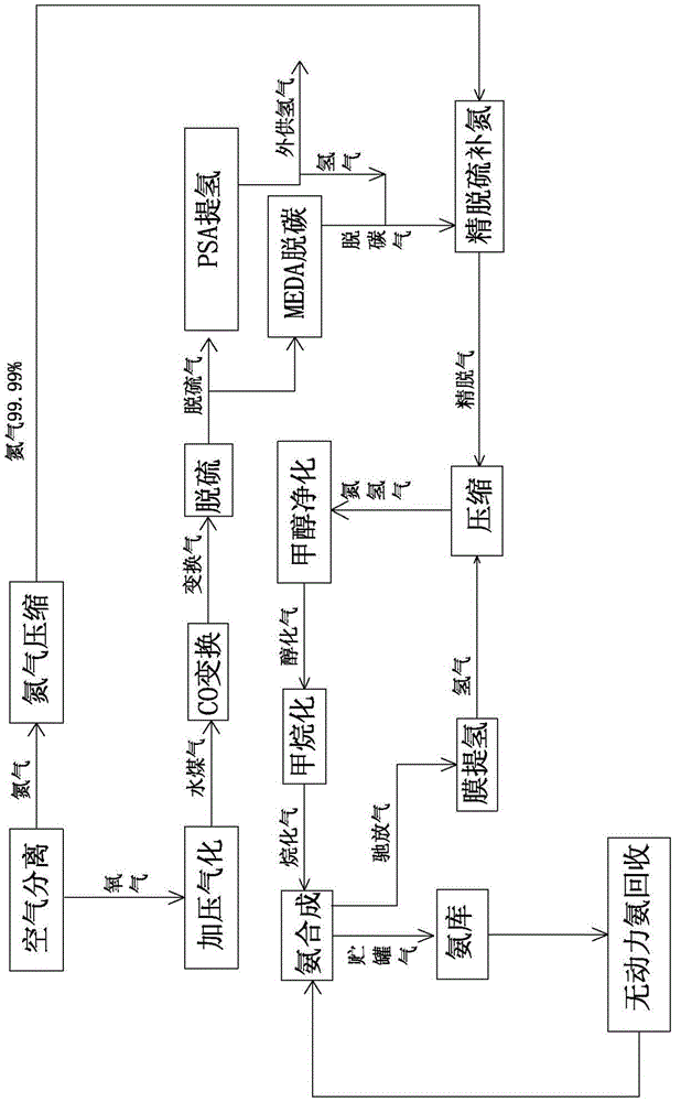
[0004] see figure 1 , the existing ammonia synthesis process includes pressurized gasification→CO shift→DDS desulfurization→PSA hydrogen extraction→MEDA decarburization→fine desulfurization and nitrogen supplementation→compression→methanol purification→methanation→ammonia synthesis and other 10 main process steps, Specifically, the current domestic coal chemical industry (production of synthesis gas and hydrogen) equipment using anthracite as raw material uses atmospheric pressure fixed-layer batch gasifiers to produce crude synthesis gas. High, large amount of waste gas and wastewater discharge, great environmental pollution

Method used


Image

  • Production process and system of high-purity hydrogen and ammonia synthesis process and system
  • Production process and system of high-purity hydrogen and ammonia synthesis process and system
  • Production process and system of high-purity hydrogen and ammonia synthesis process and system

Examples


Embodiment 1

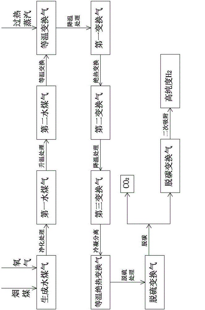
[0068] see figure 2 and image 3 , the present embodiment provides a production process of high-purity hydrogen, which uses bituminous coal as raw material, comprising the following steps:

[0069] S100: Bituminous coal generates water gas; bituminous coal and oxygen pressurized gasification produces water gas, and the CO content in the generated water gas is 65% to 75%.

[0070] In this example, bituminous coal, oxygen and water vapor are used to react to generate water gas in the gasifier, wherein the ratio of bituminous coal, oxygen and water vapor is 100:89:54, the reaction temperature is 1000-1500°C, and the gasification pressure is 0.5 to 4.0MPa. The CO content of the water gas generated by the existing anthracite gasifier is 25-40%. In the present invention, bituminous coal is used as fuel to gasify in the gasifier, so that the generated CO content reaches 65-75%. (H2+CO) reaches 90%, the temperature of the generated water gas is 160°C to 170°C, and the water conten...

Embodiment 2

[0097] Correspondingly, see Figure 4 , the present invention also provides a high-purity hydrogen production system, the system comprises a water gas generation part 1, a shift gas generation part 2, a shift gas desulfurization part 3 and a change gas decarburization and hydrogen extraction part 4, the water gas generation part 1 and Between the shift gas generating part 2, between the shift gas generating part 2 and the shift gas desulfurization part 3, and between the shift gas desulfurization part 3 and the shift gas decarburization and hydrogen extraction part 4 are connected by pipelines.

[0098] Preferably, as an embodiment, the water gas generating part 1 includes a raw material conveying device 101, an air separation device 102 and a gasifier 103, the fuel enters the gasification furnace 103 through the raw material conveying device 101, and the oxygen separated by the air separation device 102 Entering the gasifier 103 , the bituminous coal and oxygen are pressurize...

Embodiment 3

[0106] see Figure 5 and Image 6 , the present embodiment provides a synthetic ammonia process, which adopts the steps of the high-purity hydrogen production process described in Embodiment 1 to produce high-purity hydrogen, and further includes the following steps:

[0107] Step S500 : supplementing nitrogen and removing oxygen with hydrogen; mixing the high-purity H2 obtained in step S400 with nitrogen in proportion, and then removing a trace amount of oxygen in the mixture to obtain a nitrogen-hydrogen mixture. In this step, the operating pressure is 1.2-1.4 MPa (preferably 1.3 MPa), and the operating temperature is 30-45°C (preferably 35°C).

[0108] Preferably, as an embodiment, the nitrogen in this step comes from an air separation device with a purity of 99.99% nitrogen, and the nitrogen needs to be mixed with hydrogen after being compressed.

[0109] The main purpose of this step is to supplement hydrogen and nitrogen with nitrogen in the hydrogen according to the r...


PUM


Abstract

The invention provides a production process and system of high-purity hydrogen and an ammonia synthesis process and system. The production process of high-purity hydrogen comprises the steps of generating water gas by using bituminous coal, generating shifted gas by using the water gas, desulfurizing the shifted gas, and carrying out decarbonization and hydrogen extraction on the shifted gas; the ammonia synthesis process comprises the steps of hydrogen nitrogen-feeding and deoxygenization, nitrogen-hydrogen compression and ammonia synthesis. The production system of high-purity hydrogen comprises a water gas generating part, a shifted gas generating part, a shifted gas desulfurizing part and a shifted gas decarbonization and hydrogen extraction part; and the ammonia synthesis system also comprises a hydrogen nitrogen-feeding and deoxygenization part, a nitrogen-hydrogen compression part and an ammonia synthesis part. The production process of high-purity hydrogen disclosed by the invention is short in flow, small in resistance, low in power consumption and low in operating cost; and the production system of high-purity hydrogen disclosed by the invention is high in degree of automation, less in catalyst consumption, less in species, less in operators, good in operating environment, low in operating cost and remarkable in energy saving and consumption reducing effect.

Description

technical field [0001] The invention relates to the technical field of chemical industry, in particular to a production process and system of high-purity hydrogen and an ammonia synthesis process and system which are conveniently retrofitted on existing production systems. Background technique [0002] The adjustment of raw material and power structure is an important measure for the country to carry out strategic structural adjustment of the nitrogen fertilizer industry. Its implementation can significantly reduce the production cost of hydrogen or synthetic gas for coal chemical products in my country, especially reduce the price of chemical fertilizers and realize the indirect support for agriculture. Purpose. [0003] At present, most of the nitrogen fertilizer plants using coal as raw material in my country use anthracite lump coal as raw material and adopt fixed-bed intermittent gasification technology. Due to the limitation of the distribution of coal resources in my c...

Claims


Application Information

Patent Timeline
IPC IPC(8): C10J3/00C01B3/16C01B3/50C01B3/52C01B3/56C01C1/04
CPCC01B3/16C01B3/508C01B3/52C01B3/56C01B2203/1205C01B2203/1657C01C1/04C10J3/00C10J2200/09C10J2300/0933C10J2300/1603C10K1/00C10K1/004Y02P20/10Y02P20/52
Inventor 杨献斌周毅李克录杨科任焱凯
Owner 蓝星工程有限公司
Learn More