
Electronic detector

A technology of electronic detection and electric telescopic device, which is applied in the directions of blood pressure measurement device, pulse/heart rate measurement, diagnostic recording/measurement, etc. It can solve the problems of large volume, excessive wrist strap force, large power consumption, etc., and achieve small size , wear comfortable effect

Inactive Publication Date: 2015-03-25
许建平
View PDF5 Cites 26 Cited by
  • Summary
  • Abstract
  • Description
  • Claims
  • Application Information

AI Technical Summary

Problems solved by technology

[0004] At present, the known electronic blood pressure detection devices that can accurately detect blood pressure have the defects of large volume, high power consumption, and inability to continuously monitor blood pressure, such as the air pump sphygmomanometer, which uses an inflatable air bag, so it needs The pulse pressure wave signal can be detected only when the balloon pressure is large enough, so there are defects such as large volume, high power consumption, inconvenient carrying, and not suitable for dynamic or continuous monitoring of blood pressure; another smaller volume can continuously The device for blood pressure monitoring is to artificially apply predetermined tightening force to the wristband, so that the sensor device generates a certain pressure on the skin surface to monitor blood pressure. , time, etc., therefore, under the same length of the wristband, sometimes the wearer will feel that the wristband is too strong, and the bigger problem will cause certain damage to the skin tissue and blood vessels. Sometimes the wristband If the beam force is too small, the too small beam force will reduce the resolution of the sensor device and still reduce the monitoring accuracy of the blood pressure monitoring device. Therefore, the blood pressure monitoring device has the defects of poor practicability and continuous detection accuracy cannot be guaranteed
In the same way, the existing devices for continuous or dynamic detection and monitoring of living body physiology and vital signs by wearing them on living body limbs also have the defect that the wearing force cannot be automatically adjusted.

Method used


Image

  • Electronic detector
  • Electronic detector
  • Electronic detector

Examples


Embodiment Construction

[0034] The technical solution according to the present invention will be illustrated below with reference to the accompanying drawings.

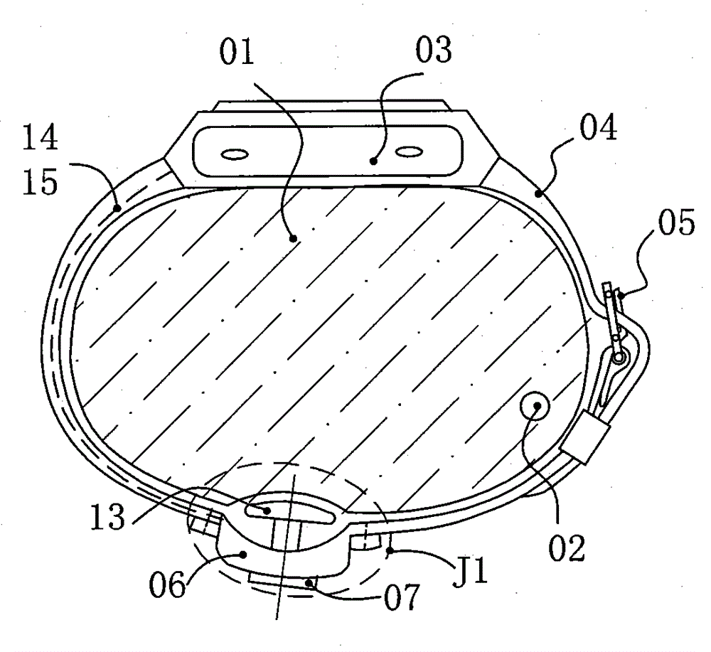
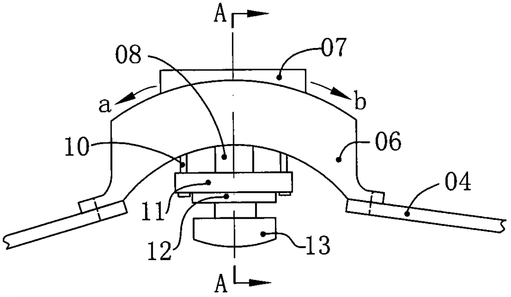
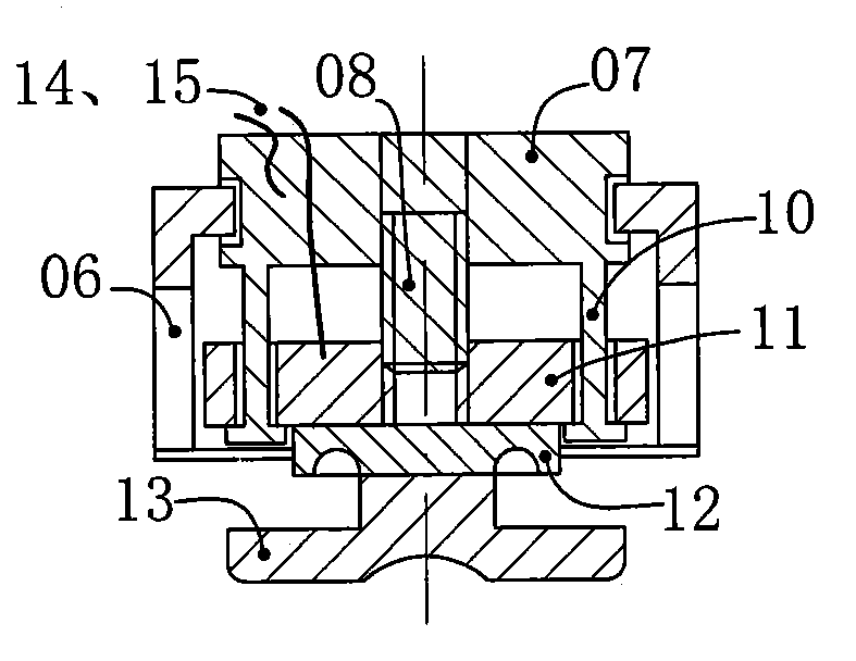
[0035] Figure 1~3 It is a structural schematic diagram of an electronic blood pressure detection device; especially a structural schematic diagram of a wrist-type or arm-type electronic blood pressure detection device in which the electric telescopic device is arranged between the wearing part and the detection end of the sensor device; wherein, 01 is a human body Wrist, 02 is the radial artery, 03 is the watch case with built-in signal processing unit or single-chip microcomputer, motor drive module, timer, display screen, button, battery, wireless data transmission / communication module, etc., 04 is the wristband, which can be made of plastic Material, leather material, metal chain, etc., 05 is the buckle, 06 is the concave shell or bracket, 07 is the stepper motor or servo motor, 08 is the rotating shaft of the stepper motor or servo moto...


PUM


Abstract

The invention relates to an in-vivo pulse, pulse waveform or blood pressure detector, a heart rate, heart sound, maternal fetal sound, lung breath sound or electrocardiosignal detector, an in-vivo internal organ or internal tissue image detector and the like, in particular to an electronic detector comprising a wearable part; the wearable part is provided with a sensing device at least; the wearable part is suitable for being put around or on an in-vivo limb; the wearable part comprises an electric telescopic device, an electric expansible device or an electric swinging device; the force of contact of the sensing device upon the surface of the in-vivo skin is adjusted through the electric telescopic device, the electric expansible device or the electric swinging device, or the length of the wearable part is adjusted through the electric telescopic device, the electric expansible device or the electric swinging device, thereby allowing detection.

Description

[0001] References to related applications [0002] The present invention is a continuation of the following Chinese invention patent application: application date: July 02, 2014, application number: 201410318106.6, title "a detection device and an electronic blood pressure detection device". Technical field [0003] The invention relates to an electronic detection device suitable for a living body, in particular to an electronic detection device worn on a limb of a living body to detect physiological and vital signs, internal organs, tissue image signals, brain wave electric signals, etc., belonging to The field of measurement technology, the field of electronic health products, the field of medical equipment, but not limited to this. Background technique [0004] At present, the known electronic blood pressure detection devices that can accurately detect blood pressure have the defects of large volume, high power consumption, and inability to continuously monitor blood pres...

Claims


Application Information

Patent Timeline
IPC IPC(8): A61B5/02A61B5/0225A61B5/0402A61B5/0476A61B7/04A61B6/00A61B8/00
CPCA61B5/02A61B5/02208A61B5/02225A61B5/0225A61B5/681A61B6/00A61B7/04A61B8/02A61B8/04A61B8/4227A61B8/4427A61B5/318A61B5/369
Inventor 许建平许文凯徐美莲
Owner 许建平
Learn More