Organic light-emitting device and preparation method for same
An electroluminescent device and luminescent technology, which is applied in the direction of electric solid-state devices, semiconductor/solid-state device manufacturing, electrical components, etc., can solve the problems of short life of light-emitting devices, material aging, failure, etc., and achieve high density and long life , Anti-corrosion effect
- Summary
- Abstract
- Description
- Claims
- Application Information
AI Technical Summary
Problems solved by technology
Method used
Image

Examples
preparation example Construction
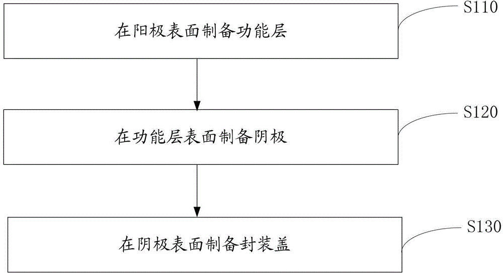
[0040] Please also see figure 2 , the preparation method of the organic electroluminescent device 100 of one embodiment, it comprises the following steps:
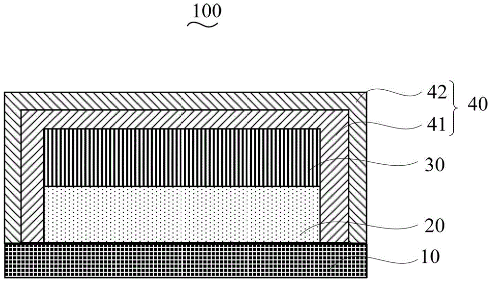
[0041] Step S110 , forming a functional layer 20 on the anode 10 .
[0042] The functional layer 20 includes a hole injection layer, a hole transport layer, a light emitting layer, an electron transport layer, and an electron injection layer stacked in sequence.
[0043]The anode 10 may be a conductive glass substrate or a conductive organic polyethylene terephthalate (PET) film substrate. The anode 10 has an ITO layer prepared with an anode pattern. In this embodiment, the thickness of the ITO layer is 100 nm. Of course, the thickness of the ITO layer is not limited to 100 nm, and other thicknesses can also be selected as required.
[0044] Before forming the functional layer 20, the surface of the anode 10 is pretreated to remove pollutants on the surface of the substrate 10, and the surface is activated to increase...
Embodiment 1
[0069] The structure prepared in this example is: ITO / NPB: MoO 3 / TCTA / TPBI:Ir(ppy) 3 / Bphen / Bphen:CsN 3 / Al / The organic electroluminescent device with the cap; wherein, the oblique bar " / " indicates a layered structure, and the colon ":" indicates doping, the same below.
[0070] The preparation method of the above-mentioned organic electroluminescent device comprises the following steps:
[0071] 1. Form a functional layer on the anode.
[0072] Anode 10 is conductive glass. The anode 10 has an ITO layer prepared with an anode pattern. The thickness of the ITO layer was 100 nm.
[0073] Before forming the functional layer 20, the surface of the anode 10 is pretreated to remove pollutants on the surface of the substrate 10, and the surface is activated to increase the oxygen content on the surface of the anode 10 to improve the work function of the surface of the anode 10. Specifically, the anode 10 is ultrasonically cleaned for 5 minutes with acetone-free, ethanol, io...
Embodiment 2
[0088] The structure prepared in this example is: ITO / NPB: MoO 3 / TCTA / TPBI:Ir(ppy) 3 / Bphen / Bphen:CsN 3 / Al / organic electroluminescent devices with capsulation.
[0089] The preparation method of the above-mentioned organic electroluminescent device comprises the following steps:
[0090] 1. Form a functional layer on the anode.
[0091] Anode 10 is conductive glass. The anode 10 has an ITO layer prepared with an anode pattern. The thickness of the ITO layer was 100 nm.
[0092] Before forming the functional layer 20, the surface of the anode 10 is pretreated to remove pollutants on the surface of the substrate 10, and the surface is activated to increase the oxygen content on the surface of the anode 10 to improve the work function of the surface of the anode 10. Specifically, the anode 10 is ultrasonically cleaned for 5 minutes with acetone-free, ethanol, ionized water, and ethanol in sequence, and then blown dry with nitrogen and oven-dried.
[0093] The material o...
PUM
| Property | Measurement | Unit |
|---|---|---|
| Thickness | aaaaa | aaaaa |
| Thickness | aaaaa | aaaaa |
| Thickness | aaaaa | aaaaa |
Abstract
Description
Claims
Application Information
 - R&D
- Intellectual Property
- Life Sciences
- Materials
- Tech Scout
- Unparalleled Data Quality
- Higher Quality Content
- 60% Fewer Hallucinations
Browse by: Latest US Patents, China's latest patents, Technical Efficacy Thesaurus, Application Domain, Technology Topic, Popular Technical Reports.
© 2025 PatSnap. All rights reserved.Legal|Privacy policy|Modern Slavery Act Transparency Statement|Sitemap|About US| Contact US: help@patsnap.com