Self energy taking power supply device

A power supply device and self-energy technology, which is applied in the direction of electrical components, electronic switches, pulse technology, etc., to achieve the effects of small capacitance loss, strong self-healing, and improved safety factor

Inactive Publication Date: 2014-11-19
平高集团智能电力科技有限公司 +2
View PDF3 Cites 7 Cited by
  • Summary
  • Abstract
  • Description
  • Claims
  • Application Information

AI Technical Summary

Problems solved by technology

[0004] The purpose of the present invention is to provide a self-energy-capturing power supply ...

Method used


Image

  • Self energy taking power supply device
  • Self energy taking power supply device
  • Self energy taking power supply device

Examples


Embodiment Construction

[0020] The present invention will be described in further detail below in conjunction with the accompanying drawings.

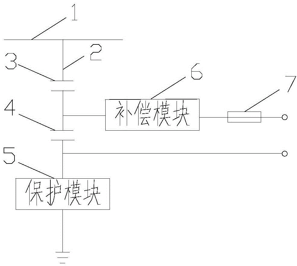
[0021] The self-energy power supply device includes series capacitors for connecting power supply and distribution lines, and the series capacitors include high-voltage capacitors and low-voltage capacitors; both ends of the low-voltage capacitors are used for power collection. The terminal used to take power can be directly connected to the smart switch monitoring device, which is suitable for the smart switch monitoring device using AC power supply; it can also be connected to the smart switch monitoring device after the rectification and filtering unit, which is suitable for the smart switch monitoring device using DC power supply. The self-energy source can be in the form of single-phase or three-phase, such as Figure 4 As shown, the structure of each phase is the same as that of single phase.

[0022] Specifically, such as figure 1 As shown, the self-...


PUM


Abstract

The invention relates to a self energy taking power supply device. A self energy taking capacitor adopts a capacitor voltage dividing form, the stability is high, and the cost is low; and meanwhile no transformer is connected to two ends of a low-voltage capacitor, the volume and weight of a power supply and an intelligent switch are greatly reduced, and the electromagnetic interference and visual pollution due to overhead line distribution network layout are reduced. The self energy taking power supply device takes power from a wire inlet side of a high-voltage switch, is unaffected by a line load, and can also provide a switch operating power supply when power supply and distribution lines fail.

Description

technical field [0001] The invention relates to a self-energy-taking power supply device, which is used in the field of intelligent switches. Background technique [0002] At present, there are mainly the following types of intelligent switch energy harvesting technology: 1. Voltage transformer type, which can be used to supply power to the automatic monitoring device of overhead line distribution network, but due to its vulnerability to external environment, system impact, pouring quality and other aspects Influenced by various factors, many voltage transformer explosion accidents occurred during operation, which seriously affected the safe operation of distribution lines. 2. The current transformer type, which uses the primary side to induce the high-voltage bus current to obtain the secondary side electric power output. When the bus current changes from several amperes to several thousand amperes, the working power obtained by this method is extremely unstable. When the ...

Claims


Application Information

Patent Timeline
IPC IPC(8): H03K17/08
Inventor 王静丽武可吴军辉郜延伟金光耀禹锦绣张森林马鹏超黄国灿申庆雷
Owner 平高集团智能电力科技有限公司
Why Eureka
Try Eureka