
Shield synchronous grouting construction method and construction material

A technology of synchronous grouting and construction method, which is applied in earthwork drilling, shaft lining, tunnel lining, etc. It can solve the problems of large ground subsidence, easy segregation, and large loss of single liquid slurry, so as to prevent floating and deformation, and easy Guaranteed grouting volume and short initial setting time

Active Publication Date: 2014-10-01
CHINA RAILWAY 15TH CONSTR BUREAU GRP
View PDF5 Cites 31 Cited by
  • Summary
  • Abstract
  • Description
  • Claims
  • Application Information

AI Technical Summary

Problems solved by technology

[0004] 1) Synchronous single-injection slurry has low early strength, lacks chemical stability in the later stage, and is easy to segregate, which cannot effectively control the uplift of the tunnel after it breaks away from the shield tail and maintain the longitudinal stability of the tunnel in the later stage
2) The amount of grouting loss is large, and the total amount of grouting is not easy to control, especially when the shield passes through the water-rich stratum, it is difficult to completely fill the gap between the segment and the excavation wall due to factors such as the large loss of single liquid grout Clearance, easy to cause excessive ground subsidence
3) The initial setting time of single liquid slurry is long, and it cannot provide early strength quickly
4) Single liquid slurry is easy to segregate, causing difficulties in transportation and storage

Method used


Image

  • Shield synchronous grouting construction method and construction material
  • Shield synchronous grouting construction method and construction material
  • Shield synchronous grouting construction method and construction material

Examples


Embodiment Construction

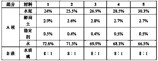
[0021] The invention provides a shield synchronous grouting construction material, including A liquid and B liquid, wherein, the A liquid includes 25.5wt% cement, 2.6wt% bentonite, 0.4wt% stabilizer and 71.5wt% the water; the B liquid is water glass, and the volume ratio of the A liquid and the B liquid is 8:1~15:1. The stabilizer is one or more of naphthalene-based superplasticizers, polycarboxylic acid-based superplasticizers, melamine-based superplasticizers or sulfamic acid-based superplasticizers.

[0022] The initial setting time of the double-liquid slurry composed of the A liquid and the B liquid is 10s to 14s; the 28d uniaxial compressive strength is not less than 2.5Mpa; it has good water dispersion resistance and injectability, and the gelation time is generally 4 ~10 hours, not less than 0.2MPa per day (equivalent to the unconfined compressive strength of soft rock formations), not less than 2.5MPa (slightly greater than the natural compressive strength of strongly...


PUM


Abstract

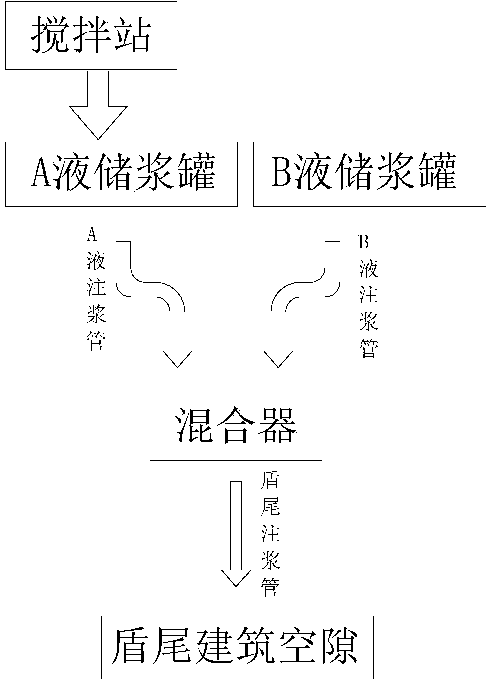
The invention discloses a shield synchronous grouting construction method and a construction material. The construction material comprises liquid A and liquid B, wherein the liquid A comprises 25.5 weight percent of cement, 2.6 weight percent of bentonite, 0.4 weight percent of stabilizing agents and 71.5 weight percent of water; the liquid B is water glass; and the volume ratio of the liquid A to the liquid B is 8:1-15:1. During synchronous grouting construction, the liquid A is prepared in a mixing station, and the liquid A and the liquid B are respectively conveyed into a liquid A slurry storage tank and a liquid B slurry storage tank which are arranged on a shield machine; the liquid A and the liquid B are respectively conveyed into a mixer positioned at the shield tail part of the shield machine through a liquid A slurry injection pipe and a liquid B slurry injection pipe; and the liquid A and / or the liquid B in the mixer are / is synchronously injected into a shield tail building gap through a shield tail slurry injection pipe. The shield synchronous grouting construction method solves various problems in subsequent grouting, synchronous single slurry injection, in-time grouting and secondary grouting in the prior art through utilizing good performance of the liquid A and the liquid B before and after the mixing of the liquid A and the liquid B and combining a primary synchronous grouting process.

Description

technical field [0001] The invention is used in the field of tunnel construction, and in particular relates to a shield synchronous grouting construction method and construction materials. Background technique [0002] During the construction of the shield tunnel, when the shield tail comes out of the assembled shield segment, it will inevitably cause a building gap between the segment lining and the soil. At this time, timely shield tail grouting is required to prevent The soil around the shield segment is loosened, and at the same time, the wrapping effect of the soil on the lining structure of the shield segment is strengthened, so as to avoid the phenomenon of local stress concentration in the segment structure due to the lack of necessary resistance. Shield tail grouting refers to that in the process of shield tunneling construction, after the tunnel lining segments are assembled and the tunnel comes out of the shield tail, under a certain grouting pressure, an appropri...

Claims


Application Information

Patent Timeline
IPC IPC(8): E21D11/10
Inventor 郑勇乔水旺赵林郭志峰李辉郭县华
Owner CHINA RAILWAY 15TH CONSTR BUREAU GRP
Learn More