
Thin-wall part complex working condition machining state monitoring method

A technology of processing state and complex working conditions, which is applied in the direction of instruments, computer control, simulators, etc., can solve the problems of complex thin-walled parts, single processing state monitoring items, and inability to reflect the coupling effect of various processing states, so as to ensure the quality of processing Quality, cost reduction effect

Active Publication Date: 2014-07-23
NANJING UNIV OF AERONAUTICS & ASTRONAUTICS
View PDF4 Cites 14 Cited by
  • Summary
  • Abstract
  • Description
  • Claims
  • Application Information

AI Technical Summary

Problems solved by technology

[0005] The purpose of the present invention is to solve the problem that the existing processing state monitoring items are single and cannot reflect the coupling effect of multiple processing states, and to invent a thin-walled part that couples multiple working conditions and monitors the processing state in real time through a support vector machine Monitoring Method of Machining Status in Complicated Working Conditions

Method used


Image

  • Thin-wall part complex working condition machining state monitoring method
  • Thin-wall part complex working condition machining state monitoring method
  • Thin-wall part complex working condition machining state monitoring method

Examples


Embodiment Construction

[0040] The following structural drawings and embodiments further illustrate the present invention.

[0041] like Figure 1-13 shown.

[0042] In this embodiment, aluminum alloy is used as the cutting test material, and a cemented carbide end mill is used as the cutting tool. The Kistler amplifier is used to collect mechanical signals, and the acceleration sensor is used to collect vibration signals.

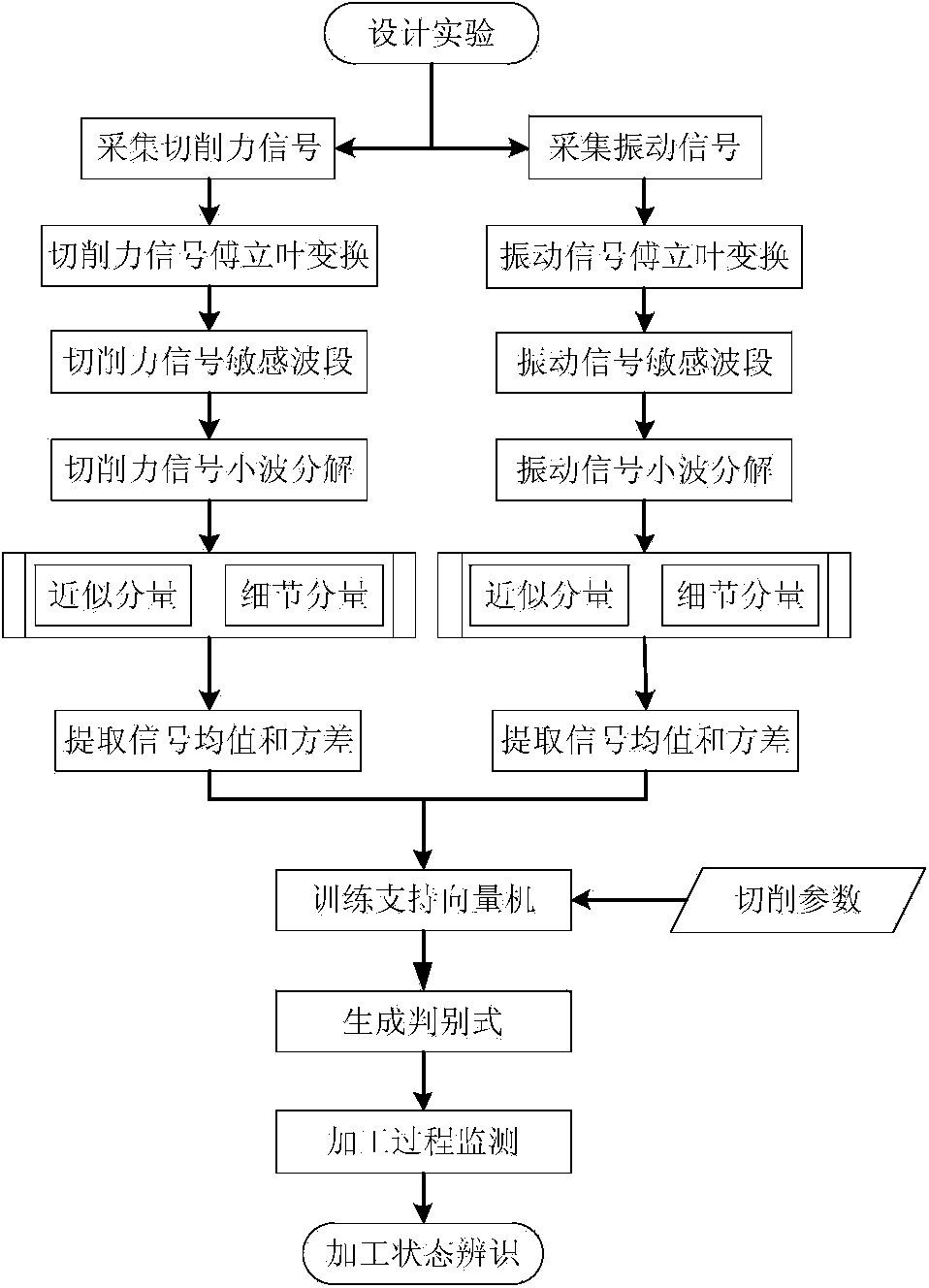
[0043] figure 1 It is a flow chart of the complex working condition processing state monitoring method based on multi-sensor fusion and support vector machine of the present invention. like figure 1 As shown, a method for monitoring the processing status of thin-walled parts under complex working conditions, which includes the following steps:

[0044] 1. Test environment

[0045] The test conditions of this embodiment include a five-axis numerical control machine tool, a three-way dynamometer, and an acceleration sensor; two cutting tools are used: a non-wearing tool; and a...


PUM


Abstract

A thin-wall part complex working condition machining state monitoring method is characterized in that cutting force signals and vibration signals are collected first through experiments, then the two kinds of signals are subjected to Fourier transformation and filtering respectively, sensitive frequency of a machining state is obtained, an approximate component and a detailed component of signals of an appointed frequency band are obtained through wavelet transformation, statistics data comprising an average value and a variance are extracted, information fusion is carried out on a feature layer, and cutting parameters and signal statistics data are used as input vectors for machining state identifying. Machining state identifying is carried out through a support vector machine algorithm, a support vector machine is trained through collected data, discriminants of different machining states are obtained, and monitoring and identifying on multiple machining process states with coupling effect such as tool abrasion, tool deforming and workpiece deforming are achieved. Machining cost can be well lowered, and machining quality is guaranteed.

Description

technical field [0001] The invention relates to an on-line detection and discrimination technology of mechanical processing state, which belongs to the technical field of numerical control processing, in particular to a method for simultaneously monitoring tool wear and workpiece deformation by using multiple sensors in side milling processing, specifically a method based on Multi-sensor fusion and support vector machine processing status monitoring method for thin-walled parts under complex working conditions. Background technique [0002] The rapid development of CNC machine tools in recent years has made CNC machining tend to be digitized, virtualized, automated and intelligent, and the processing efficiency has been greatly improved, especially high-end CNC machine tools have become indispensable in the field of CNC machining. CNC machining capability is one of the important indicators to measure processing equipment. For high-cost, high-precision parts such as aircraft...

Claims


Application Information

Patent Timeline
IPC IPC(8): G05B19/406
Inventor 刘长青李迎光周鑫牟文平
Owner NANJING UNIV OF AERONAUTICS & ASTRONAUTICS
Learn More