
Extreme ultraviolet lithography light source collection and illumination system

A technology for extreme ultraviolet lithography and lighting systems, applied in the field of extreme ultraviolet lithography light source collection and lighting systems, can solve the problems of short axial distance, difficult processing of hyperbolic reflective surfaces, and no practical approval, and achieve easy Processing and assembly, the effect of reducing manufacturing costs

Inactive Publication Date: 2014-06-18
HARBIN INST OF TECH
View PDF13 Cites 5 Cited by
  • Summary
  • Abstract
  • Description
  • Claims
  • Application Information

AI Technical Summary

Problems solved by technology

[0006] However, due to its special structural form, the axial distance between the Wolter type collection system and the light source is very close, which brings certain difficulties to the design of the light source decontamination system, and the processing of the hyperbolic reflective surface at the front of the mirror body is difficult , which must be considered in terms of manufacturing and cost
The extreme ultraviolet compound eye lighting system proposed in the early stage has not been widely recognized for its practicality due to the difficulty in processing and assembling each tiny mirror element.

Method used


Image

  • Extreme ultraviolet lithography light source collection and illumination system
  • Extreme ultraviolet lithography light source collection and illumination system
  • Extreme ultraviolet lithography light source collection and illumination system

Examples


Embodiment Construction

[0027] combine figure 1 and figure 2 , an embodiment of the present invention is given, mainly as a further detailed description of the present invention, rather than limiting the scope of the present invention.

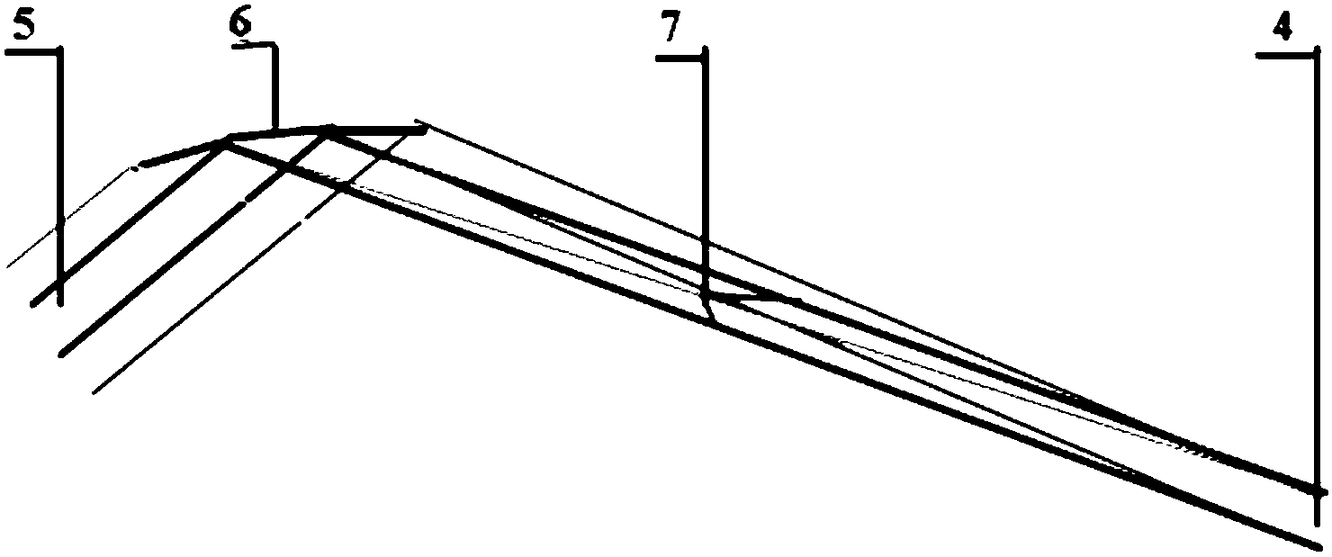
[0028] Such as figure 1 As shown, the extreme ultraviolet lithography light source collection and illumination system provided in this embodiment includes a light source 1 , a front reflector group 2 , a rear reflector group 3 and an illumination spot 4 . The illumination aperture angle of the mask plate should be matched with the object space aperture angle of the projection system. Based on this condition, it can be preliminarily determined that the image space numerical aperture of the light source collection and illumination system in this embodiment is 0.3 (approximately the system rear end surface For the half angle radian value of the illumination spot 4). If the light source is a laser plasma light source (LPP), because the size of the plasma is very smal...


PUM

PropertyMeasurementUnit
Lengthaaaaaaaaaa
Radial lengthaaaaaaaaaa

Abstract

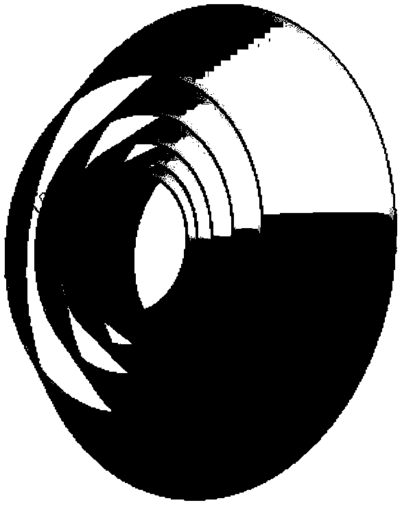
The invention provides an extreme ultraviolet lithography light source collection and illumination system. The extreme ultraviolet lithography light source collection and illumination system comprises two parts including a front-end reflection mirror set and a rear-end reflection mirror set, wherein the front-end reflection mirror set and the rear-end reflection mirror set are mounted and fixed by a supporting structure. Each layer of a reflection surface in the front-end reflection mirror set is formed by rotating different parabolic segments around the optical axis; the center of an extreme ultraviolet light source is located on a focal plane of a parabola and is located on the optical axis. Light emitted by a light source is reflected by each parabola to be emitted by a parallel light path; each annular conical surface of the rear-end reflection mirror set is used for separating the parallel light path emitted by the front-end reflection mirror set into a plurality of narrow and thin parallel light paths and all the parallel light paths are reflected to a final illumination point. According to the extreme ultraviolet lithography light source collection and illumination system, the light is collected and the function of an illumination system can also be realized to finish light bean reshaping and spectrum filtering work a good illumination condition is provided for the aeration of a mask plate; a collection system and the illumination system are integrated so that the whole working space can be diminished and the structure of an optical system is compact.

Description

technical field [0001] The invention belongs to the field of advanced extreme ultraviolet lithography technology, and relates to an extreme ultraviolet lithography light source collection and lighting system, which is used for light collection of plasma extreme ultraviolet light source, shaping and spectral filtering of converging light spots, so as to achieve good mask plate lighting effect. Background technique [0002] EUV / soft X-ray lithography is considered to be one of the most promising lithography technologies in the next generation, and the light source collection system and illumination system are important components of EUV lithography machines. [0003] From the point of view of usage, the collection system is not a pure imaging system. Its purpose is not to image the plasma light source to the intermediate focus, but to simply converge the extreme ultraviolet light emitted by it to the intermediate focus, and meet the imaging requirements. Under the premise of ...

Claims


Application Information

Patent Timeline
IPC IPC(8): G03F7/20G02B17/06
Inventor 张树青朱亮张明祎
Owner HARBIN INST OF TECH
Learn More