
Distributed optical fiber temperature and stress sensing device

A stress sensing, optical fiber distribution technology, applied in thermometers, measuring devices, thermometers with physical/chemical changes, etc., can solve the problems of narrow spectral bandwidth, affecting detection results, low measurement temperature and strain accuracy, etc. flexible effects

Inactive Publication Date: 2014-03-05
SHANDONG UNIV
View PDF3 Cites 16 Cited by
  • Summary
  • Abstract
  • Description
  • Claims
  • Application Information

AI Technical Summary

Problems solved by technology

Although the fully distributed optical fiber Brillouin time domain analyzer can measure temperature and strain at the same time, there are cross effects, which affect the detection results
The Newson team at the University of Southampton in the United Kingdom used a narrow-band laser source to measure temperature using the back-spontaneous anti-Stokes Raman scattering of optical fibers and used the spontaneous fiber Brillouin scattering effect to measure strain (see M.N.Allahbabi, Y.T.Cho and T.P.Newson, Simulataneous Distributed Measurements of Temperature and Strain using Spontaneous Raman and BrillouinScattering, Optics Letters, 2005, 1June, p.1276-1278), but due to the narrow spectral bandwidth of fiber Brillouin scattering, the accuracy of measuring temperature and strain is low

Method used


Image

  • Distributed optical fiber temperature and stress sensing device

Examples


Embodiment

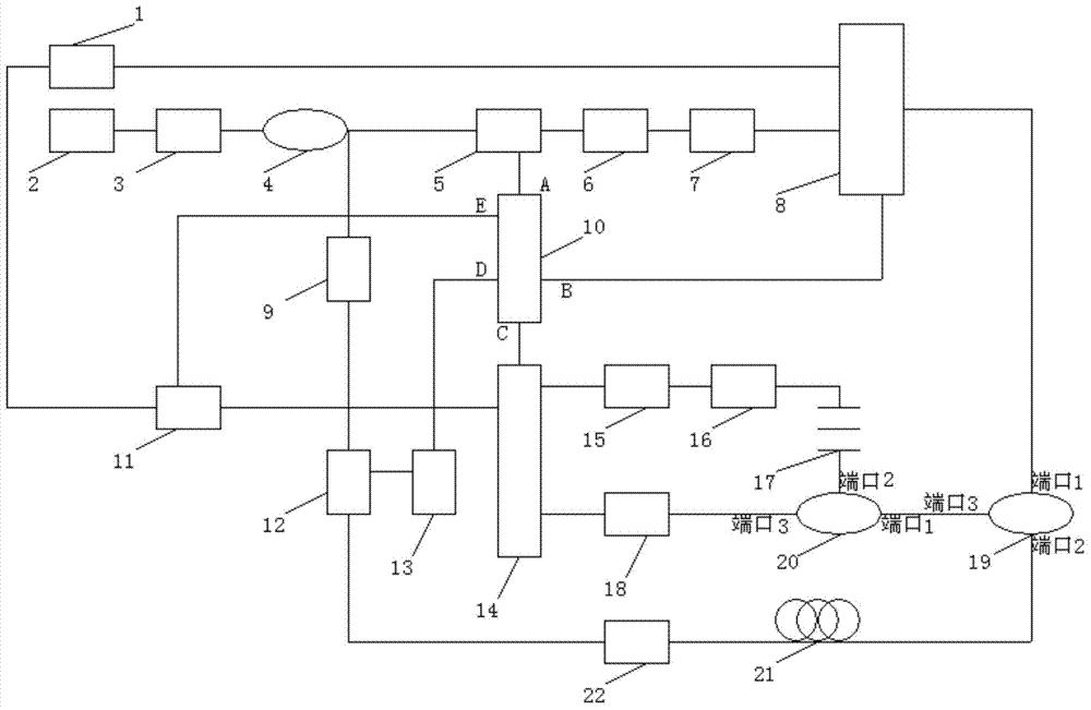
[0048] Such as figure 1 As shown, a distributed optical fiber temperature and stress sensing device includes a pulsed laser 1, a semiconductor laser 2, an optical isolator A3, an optical coupler 4, an acousto-optic modulator 5, a bait-doped fiber amplifier 6, and a polarizer 7 , Optical switch 8, polarization controller 9, signal generator 10, relay 11, electro-optic modulator 12, microwave source 13, data acquisition card 14, photodetector A15, B18, Raman filter 16, fiber Bragg grating 17, Circulator A19, B20, sensor fiber 21, optical isolator B22, characterized in that the output end of the pulse laser 1 is connected to one input end of the optical switch 8, and the other synchronous pulse output end of the pulse laser 1 is connected to the input end of the relay 11. Connected; the output end of the semiconductor laser 2 is connected to the input end of the optical isolator A3, the output end of the optical isolator A3 is connected to the input end of the 2×2 optical coupler...


PUM

PropertyMeasurementUnit
Line widthaaaaaaaaaa
Wavelengthaaaaaaaaaa
Pulse widthaaaaaaaaaa

Abstract

The invention discloses a distributed optical fiber temperature and stress sensing device, and belongs to the technical field of optical fiber sensing. The device comprises a pulse laser and the like. The pulse laser is connected with an optical switch and a relay. A semiconductor laser is sequentially connected with an optical isolator A and an optical coupler, the optical coupler is sequentially connected with an acoustic optical modulator, an erbium-doped fiber amplifier and a scrambler, the scrambler is connected with the optical switch, and the optical switch is connected with a circulator A. The other output of the optical coupler is sequentially connected with a polarization controller, an electro-optical modulator and an optical isolator B, and then is connected with the circulator A through sensor fibers. A signal generator is sequentially connected to the acoustic optical modulator, the optical switch, a data collection card, a microwave source and a relay. The microwave source is connected with the electro-optical modulator. The circulator A is connected with the circulator B which is sequentially connected with a fiber Bragg grating, a Raman filter and a photoelectric detector A, and the photoelectric detector A is connected with the data collection card. The circulator B is sequentially connected with a photoelectric detector B and the data collection card. The distributed optical fiber temperature and stress sensing device can achieve simultaneous measurement on temperature and stress in a long-distance and distributed mode.

Description

Technical field [0001] The invention relates to a distributed temperature and stress sensing device, belonging to the technical field of optical fiber sensing. Background technique [0002] For a long time, in the engineering field at home and abroad, large civil constructions, bridges, tunnels and power cables have mainly used electrical strain gauges and thermistors as strain and temperature sensors. Each sensor requires wires to form a large detection network with a complex structure. This type of sensor itself is charged and is inherently unsafe. It is susceptible to electromagnetic interference, corrosion, and cannot be positioned. It is greatly affected by the environment and is not suitable for use in harsh environments, nor is it suitable for use in geological disasters and fire sites. . [0003] The optical fiber itself is non-charged, anti-electromagnetic, resistant to radiation, resistant to high voltage, does not generate electric sparks, and has good insulation charac...

Claims


Application Information

Patent Timeline
IPC IPC(8): G01K11/32G01L1/24G01K11/3206G01K11/322G01K11/324
Inventor 常军罗沙王宗良蒋硕贾传武王福鹏田均强刘永宁孙柏宁
Owner SHANDONG UNIV
Learn More