
Low-loss large-effective area single mode fiber and manufacturing method thereof

An effective area, single-mode fiber technology, used in cladding fibers, manufacturing tools, glass manufacturing equipment, etc. Linearity, reduce optical power density, and increase the effect of effective area

Active Publication Date: 2015-05-13
FENGHUO COMM SCI & TECH CO LTD +1
View PDF9 Cites 1 Cited by
  • Summary
  • Abstract
  • Description
  • Claims
  • Application Information

AI Technical Summary

Problems solved by technology

The patented optical fiber has a high loss coefficient and a small effective area, which cannot meet the transmission requirements of 100G and super 100G high-speed communication systems
[0025] The U.S. Patent No. US7524780 proposes a low-loss optical fiber and its manufacturing method. The patent diffuses alkali metal with a molar concentration of 0.035% in quartz glass. The loss coefficient of the patented optical fiber at a wavelength of 1550nm is less than 0.180dB / km, but there is no Key indicators such as mode field diameter and effective area
[0026] The U.S. Patent No. US8315493 proposes a manufacturing method of low-loss single-mode optical fiber, which adopts VAD / MCVD process technology, and the core is prepared by VAD process. The refractive index difference between the core and the pure silica cladding is less than 0.2% , the inner cladding is prepared by MCVD, and the refractive index of the inner cladding relative to pure silica glass is concave in the range of 0 to -0.2%. Less than 0.175dB / km, but due to the low efficiency of MCVD fluorine doping, it is not suitable for large-scale production
[0027] The U.S. patent with publication number US20130188917 and patent number US7524780 proposes a method for manufacturing an optical fiber preform, which introduces an alkali metal modifier with a molar concentration of 0.2% to 0.5% in the core region to reduce the glass transition of quartz glass The temperature Tg reduces the scattering loss of the optical fiber to reduce the optical fiber loss. Theoretically, it can break through the limit value of the loss of pure silica glass material 0.150dB / km, but this kind of process is complicated, it is easy to introduce transition metal impurities, and it is extremely easy to form opacity Chloride glass leads to increased attenuation of optical fiber, the key technology has not been solved, and it is not suitable for large-scale production
[0028] The Chinese patent No. ZL200410030019.7 proposes a super-large effective area optical fiber, the effective area of ​​which is greater than 80 μm at 1310nm wavelength 2 , 1550nm greater than 95μm 2 , up to 131.2μm 2 , but the loss coefficient of 1310nm wavelength is 0.35dB / km, the loss coefficient of 1550nm is 0.190dB / km, and the dispersion coefficient of 1550nm is 20.08ps / nm / km~20.64ps / nm / km. Although the effective area of ​​this light is large, However, the loss coefficient is large and the dispersion is also large, which cannot meet the needs of high-speed communication systems.
[0029] The Chinese patent application with the application number 201180031939.9 proposes a germanium-free core large effective area single-mode fiber with graded refractive index. The fiber core is not doped with germanium, the core refractive index has a parabolic distribution, and the cladding is made of quartz doped with fluorine. The fluorine-doped concave depth is -0.25% ~ -0.5%, the 1550nm loss coefficient is 0.15dB / km ~ 0.16dB / km, and the effective area can reach 110μm 2 Above, but its dispersion at 1550nm reaches more than 20ps / nm / km, and the cut-off wavelength of LP11 mode in the 22-meter optical cable test is above 1400nm, which makes the 1310nm~1400nm communication band unusable
[0030] The Chinese patent application with the application number 201180007436.8 proposes a large effective area optical fiber without a germanium core. The fiber core is not doped with germanium, and the core is segmented. The power distribution parameter is between 15 and 200, and the fiber can obtain a loss coefficient of 0.175dB / km, and the fiber is 100 to 160μm 2 effective area, but its bending loss is relatively large, and the raised central refractive index strengthens the optical power density, which increases the nonlinearity of the communication system. Due to the use of pure silicon core and fluorine-doped cladding, the production efficiency is low, and there is no suitable for mass production
[0031] To sum up, the existing technical solutions cannot solve the two key technical problems of system loss and nonlinearity at the same time, and are not suitable for large-scale production

Method used

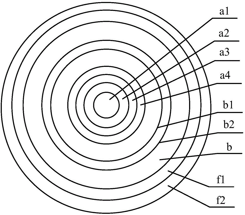
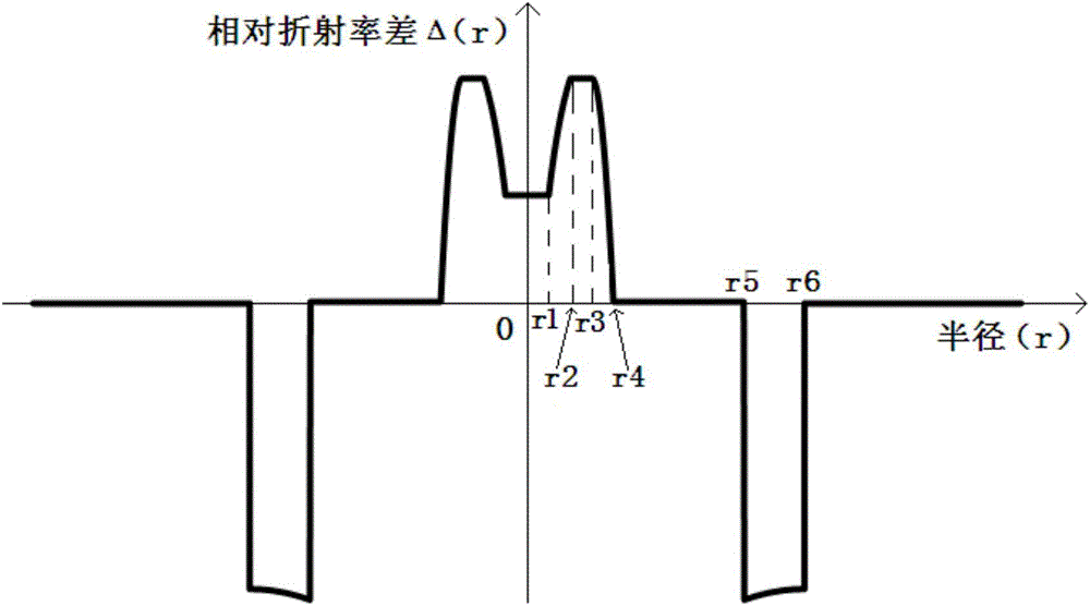
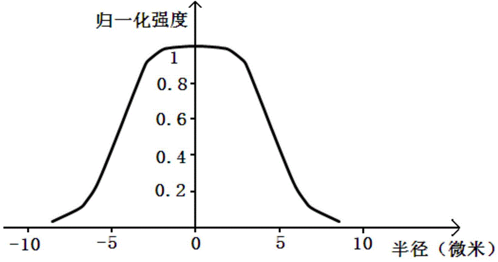

Image

  • Low-loss large-effective area single mode fiber and manufacturing method thereof
  • Low-loss large-effective area single mode fiber and manufacturing method thereof
  • Low-loss large-effective area single mode fiber and manufacturing method thereof

Examples


Embodiment 1

[0090] Silicon tetrachloride, germanium tetrachloride, high-purity oxygen, C 2 f 6 The mixed gas is passed into the deposition lathe (PCVD or VAD or MCVD or OVD), the total flow rate of the mixed gas is 13500ml / min, and the germanium-doped quartz glass core layer is generated under the high temperature of the hydrogen-oxygen flame, and the first core of the deposited core layer is area a 1 Relative refractive index difference Δ with quartz glass cladding b 1 (r) The change with the core radius r satisfies "Δ 1 (r)=c 1 "Relationship curve: 0≤r≤r 1 , r 1 = 1.50 μm, c 1 =0.10%, this part corresponds to figure 2 r in 1 The refractive index curve, forming figure 1 The first core region a in 1 ; the second core area a 2 Relative refractive index difference Δ with quartz glass cladding b 2 (r) The change with the core radius r satisfies "Δ 2 (r)=A×ln(r)+c 2 "Relationship curve: r 1 ≤r≤r 2 , r 2 =3.0μm, A=0.0022, c 2 =-0.00006, which corresponds to figure 2 r in ...

Embodiment 2

[0101] Silicon tetrachloride, germanium tetrachloride, high-purity oxygen, C 2 f 6 The mixed gas is passed into the deposition lathe (PCVD or VAD or MCVD or OVD), the total flow rate of the mixed gas is 12600ml / min, and the germanium-doped quartz glass core layer is generated under the high temperature of the hydrogen-oxygen flame, and the first core of the deposited core layer is area a 1 Relative refractive index difference Δ with quartz glass cladding b 1 (r) The change with the core radius r satisfies "Δ 1 (r)=c 1 "Relationship curve: 0≤r≤r 1 , r 1 = 1.0 μm, c 1 =0.07%, this part corresponds to figure 2 r in 1 The refractive index curve, forming figure 1 The first core region a in 1 ; the second core area a 2 Relative refractive index difference Δ with quartz glass cladding b 2 (r) The change with the core radius r satisfies "Δ 2 (r)=A×ln(r)+c 2 "Relationship curve: r 1 ≤r≤r 2 , r 2 =3.9μm, A=0.0019, c 2 =-0.00001, which corresponds to figure 2 r in 2...

Embodiment 3

[0109] Silicon tetrachloride, germanium tetrachloride, high-purity oxygen, C 2 f 6 The mixed gas is passed into the deposition lathe (PCVD or VAD or MCVD or OVD), the total flow rate of the mixed gas is 5000ml / min, and the germanium-doped quartz glass core layer is generated under the high temperature of the hydrogen-oxygen flame, and the first core of the deposited core layer area a 1 Relative refractive index difference Δ with quartz glass cladding b 1 (r) The change with the core radius r satisfies "Δ 1 (r)=c 1 "Relationship curve: 0≤r≤r 1 , r 1 = 2.0 μm, c 1 =0.15%, this part corresponds to figure 2 r in 1 The refractive index curve, forming figure 1 The first core region a in 1 ; the second core area a 2 Relative refractive index difference Δ with quartz glass cladding b 2 (r) The change with the core radius r satisfies "Δ 2 (r)=A×ln(r)+c 2 "Relationship curve: r 1 ≤r≤r 2 , r 2 =3.0μm, A=0.0025, c 2 =-0.00010, which corresponds to figure 2 r in 2 The...


PUM

PropertyMeasurementUnit
thicknessaaaaaaaaaa
diameteraaaaaaaaaa
areaaaaaaaaaaa

Abstract

The invention discloses a low-loss large-effective area single mode fiber and a manufacturing method of the low-loss large-effective area single mode fiber, and relates to the field of optical fibers. The low-loss large-effective area single mode fiber comprises a quartz glass cladding, an internal coating and an external coating, wherein the quartz glass cladding, the internal coating and the external coating are arranged in sequence from inside to outside; the inside of the quartz glass cladding comprises a first fiber core area, a second fiber core area, a third fiber core area, a fourth fiber core area and a refractive index concave cladding, wherein the first fiber core area, the second fiber core area, the third fiber core area, the fourth fiber core area and the refractive index concave cladding are arranged in sequence from inside to outside; the refractive index concave cladding is subjected to deposition through a PCVD process; the quartz glass cladding is manufactured through an OVD process or a sleeving process. According to the low-loss large-effective area single mode fiber and the manufacturing method of the low-loss large-effective area single mode fiber, the scattering loss of the low-loss large-effective area single mode fiber and the additional loss of the low-loss large-effective area single mode fiber in a bent state can be reduced; due to the fact that the spire distribution of fiber core basic mode electromagnetic field power is adjusted into flattop distribution, optical power density is reduced, the effective area of the low-loss large-effective area single mode fiber is enlarged, the nonlinearity of the low-loss large-effective area single mode fiber is reduced, the incident power of an optical fiber communication system is increased by 0.4-2.6 dB, and the low-loss large-effective area single mode fiber is suitable for mass production.

Description

technical field [0001] The invention relates to the field of optical fibers, in particular to a single-mode optical fiber with low loss and large effective area and a manufacturing method thereof. Background technique [0002] The definitions of technical terms involved in the present invention are as follows: [0003] Deposition: The chemical reaction of optical fiber raw materials in a certain environment to generate doped quartz glass. [0004] Melting: The process of gradually firing the deposited hollow glass tube into a solid glass rod under a certain heat source. [0005] Sleeve: A high-purity quartz glass tube with a certain cross-sectional area and uniform size. [0006] Substrate tube: High-purity quartz glass tube for deposition. [0007] Refractive Index Profile (RIP): The relationship between the refractive index of an optical fiber or optical fiber preform (including the fiber core rod) and its radius. [0008] Relative Refractive Index (Δ%): where n i i...

Claims


Application Information

Patent Timeline
Patent Type & Authority Patents(China)
IPC IPC(8): G02B6/02G02B6/036G02B6/028C03B37/018C03B37/025
CPCC03B2203/22Y02P40/57
Inventor 陈伟李诗愈莫琦罗文勇杜城柯一礼雷琼但融张涛胡福明
Owner FENGHUO COMM SCI & TECH CO LTD
Learn More