Low differential loss, low phase shift, high integration five-bit stepping ultra-wideband digitally controlled attenuator
A high-integration, ultra-broadband technology, applied in the field of communication, can solve problems such as occupancy, reduce system integration, and large insertion loss, and achieve the effects of reducing manufacturing costs, reducing chip area, and improving integration
- Summary
- Abstract
- Description
- Claims
- Application Information
AI Technical Summary
Problems solved by technology
Method used
Image
Examples
Embodiment 1
[0038] Embodiment 1: working state of the present invention. Embodiment 1 of the present invention is controlled by five digital signals respectively, and the different level states of the control signals input to each control terminal and the corresponding signal amplitude attenuation states are shown in the following table.
[0039]
[0040] In the table, 0 means low level and 1 means high level. It can be seen from the above table that the present invention changes the high and low level state of the input control signal through the control terminal 1, the control terminal 2, the control terminal 3, the control terminal 4 and the control terminal 5 respectively, stepping in 12.5-18GHz with a length of 1dB Within the operating frequency range and the attenuation range of 0 ~ 31dB, 32 states of low drop loss and low phase shift signal amplitude attenuation are realized.
Embodiment 2
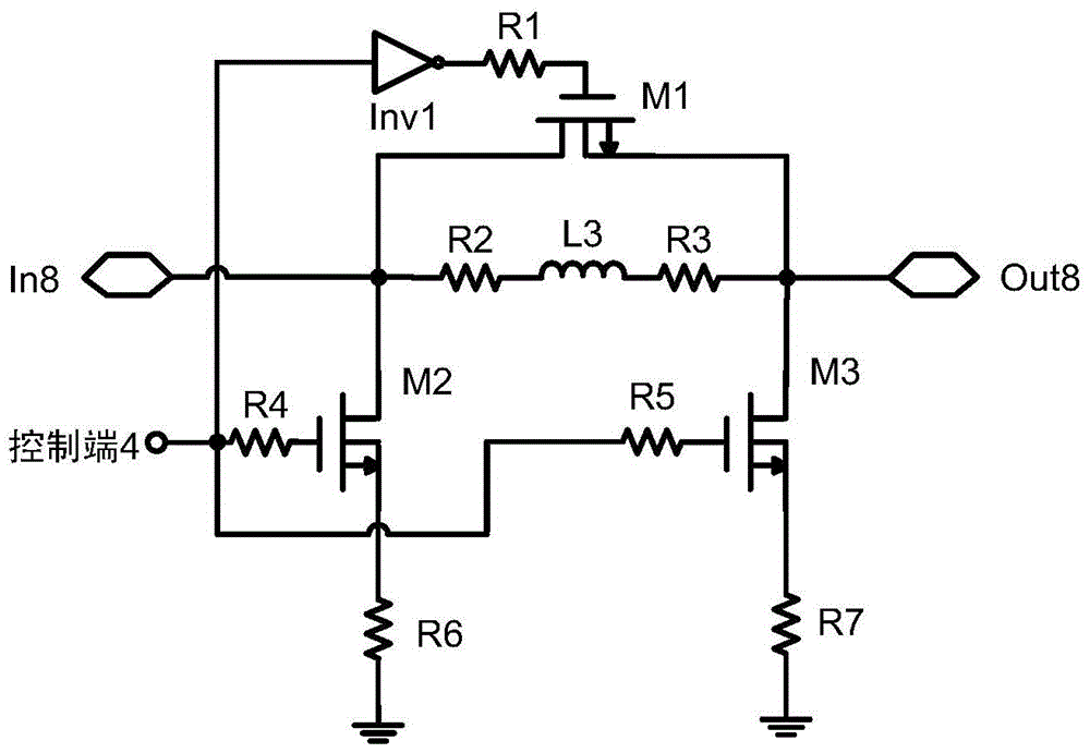
[0041] Embodiment 2: the working process of the 8dB attenuation module of the present invention. Embodiment 2 of the present invention adopts Figure 6 The MOS transistor switch shown is used as the control switch of the series branch and the parallel branch, and an additional phase shift compensation inductance network is used for phase shift compensation to achieve signal amplitude attenuation while reducing the additional phase shift of the output signal relative to the input signal . The 8dB attenuation module can be controlled at the control terminal 4 by a digital signal. When the input of the control terminal 4 is at a low level, the input of the inverter Inv1 is at a low level, the output of the inverter Inv1 is at a high level, the switch MOS transistor M1 is turned on, and both the switch MOS transistor M2 and the switch MOS transistor M3 are turned off. The 8dB attenuation module is in the reference state. When the input of the control terminal 4 is at a high lev...
Embodiment 3
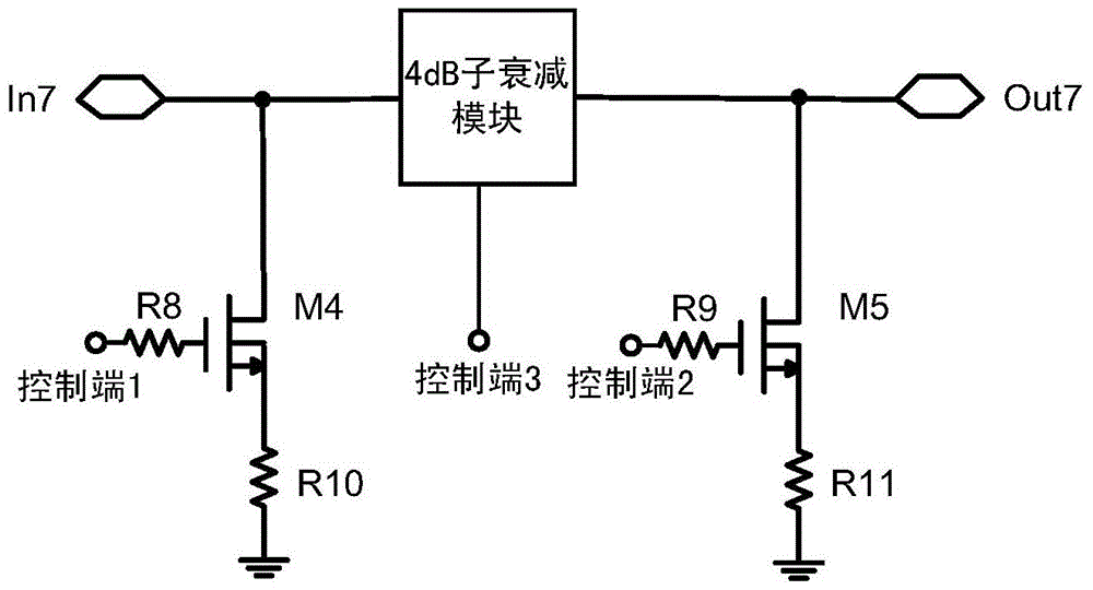
[0042] Embodiment 3: the working process of the 0~7dB combined attenuation mode of the present invention. Embodiment 3 of the present invention adopts Figure 6The MOS transistor switch shown serves as the control switch for the branch circuit, consisting of a Figure 4 The 4dB sub-attenuator module shown. The 0-7dB combined attenuation module is controlled by three digital signals at control terminal 1, control terminal 2 and control terminal 3 respectively. When the input of control terminal 1, control terminal 2, and control terminal 3 are all low level, the input of inverter Inv2 is low level, the output of inverter Inv2 is high level, switching MOS transistor M6 is turned on, and switching MOS transistor M4 , the switching MOS transistor M5 and the switching MOS transistor M7 are all turned off, and the 0-7dB combined attenuation module is in a reference state. When the input of control terminal 1 is high level, and the input of control terminal 2 and control terminal ...
PUM
 Abstract
Description
Claims
Application Information
 - R&D
- Intellectual Property
- Life Sciences
- Materials
- Tech Scout
- Unparalleled Data Quality
- Higher Quality Content
- 60% Fewer Hallucinations
Browse by: Latest US Patents, China's latest patents, Technical Efficacy Thesaurus, Application Domain, Technology Topic, Popular Technical Reports.
© 2025 PatSnap. All rights reserved.Legal|Privacy policy|Modern Slavery Act Transparency Statement|Sitemap|About US| Contact US: help@patsnap.com


