
Array substrate, manufacturing method thereof, and display device

The technology of an array substrate and a manufacturing method is applied in the fields of an array substrate, a manufacturing method thereof and a display device, which can solve the problems of high manufacturing cost and complicated manufacturing process, and achieve the effects of low manufacturing cost and simple manufacturing process.

Active Publication Date: 2013-10-16
BOE TECH GRP CO LTD
View PDF3 Cites 30 Cited by
  • Summary
  • Abstract
  • Description
  • Claims
  • Application Information

AI Technical Summary

Problems solved by technology

[0005] The technical problems to be solved by the present invention include, aiming at the problems of complex manufacturing process and high manufacturing cost of the existing oxide thin film transistor array substrate, providing a method for manufacturing an array substrate with simple manufacturing process and low manufacturing cost

Method used


Image

  • Array substrate, manufacturing method thereof, and display device
  • Array substrate, manufacturing method thereof, and display device
  • Array substrate, manufacturing method thereof, and display device

Examples


Embodiment 1

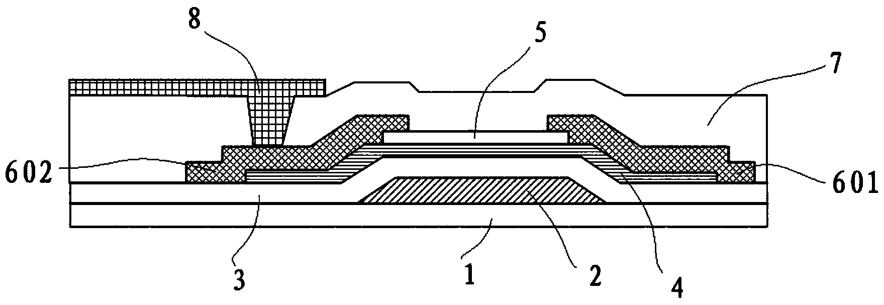
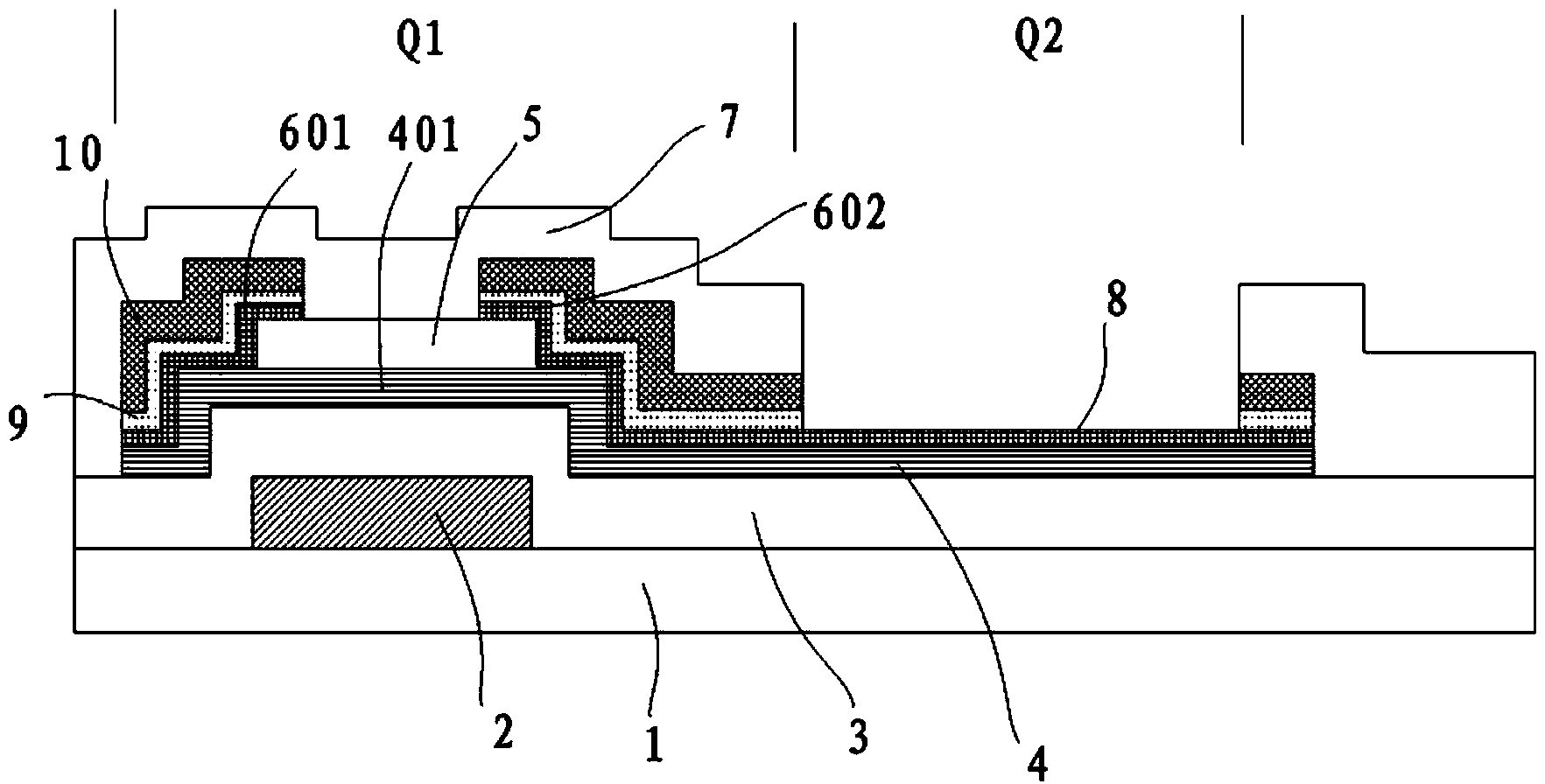
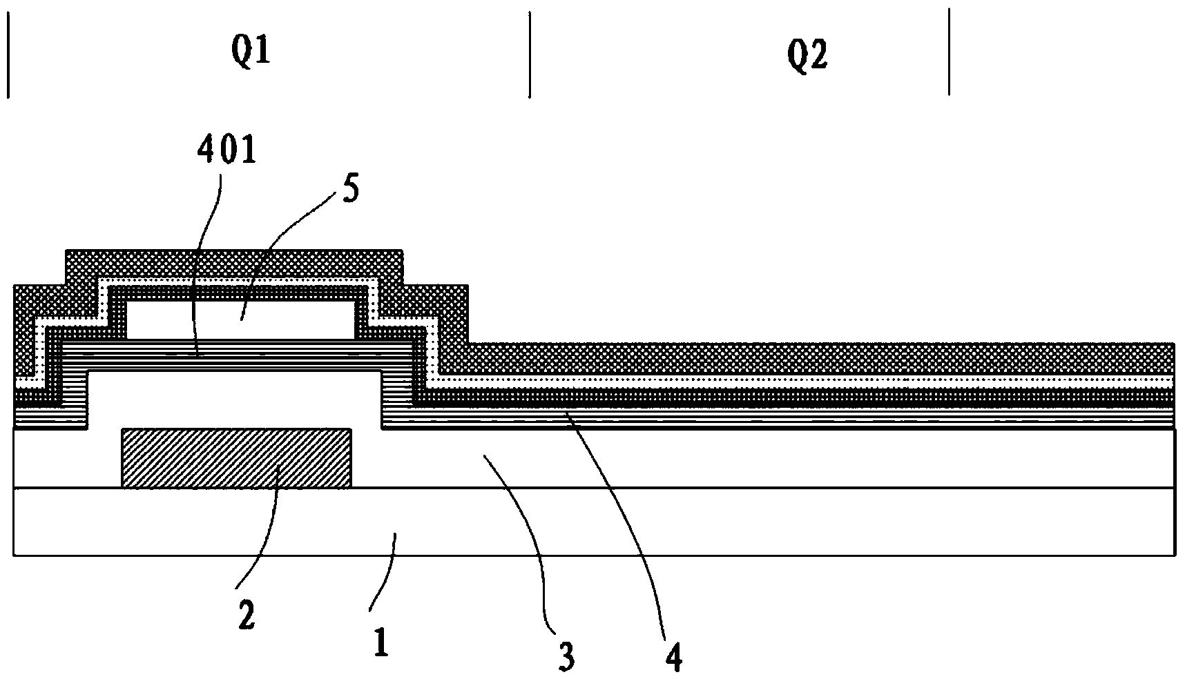
[0053] Such as figure 2 As shown, this embodiment provides an array substrate, the array substrate includes a thin film transistor area Q1 and a display area Q2, the thin film transistor area Q1 is provided with a thin film transistor, and the thin film transistor includes: a gate 2, a gate insulating layer 3, The active layer 4 , wherein the part of the active layer 4 corresponding to the gate 2 is the active region 401 . Wherein, the gate 2 is located on the substrate 1 , the gate insulating layer 3 covers the gate 2 , and the active layer 4 is located on the gate insulating layer 3 .

[0054]Preferably, the material of the active region 401 (of course, the material of the active layer 4 ) is metal oxide semiconductor. For example, its material may be indium gallium zinc oxide, indium zinc oxide or indium gallium tin oxide, preferably indium gallium zinc oxide or indium zinc oxide; the thickness of the active layer 4 is preferably between 10 nm and 100 nm. It should be no...

Embodiment 2

[0070] This embodiment provides a method for fabricating an array substrate, the array substrate comprising: a gate 2, a gate insulating layer 3, a source 601, a drain 602, a pixel electrode 8 and an active region 401, such as Figures 3 to 10 As shown, it specifically includes the following steps:

[0071] S01, forming a pattern including the gate 2 on the substrate 1 through a patterning process. The patterning process generally includes processes such as photoresist coating, exposure, development, etching, and photoresist stripping. Wherein, the material of the gate 2 is formed by one or more materials selected from molybdenum (Mo), molybdenum-niobium alloy (MoNb), aluminum (Al), aluminum-neodymium alloy (AlNd), titanium (Ti), and copper (Cu). single-layer or multi-layer composite laminates. It is preferably a single-layer or multi-layer composite film composed of molybdenum (Mo), aluminum (Al) or an alloy containing molybdenum (Mo) and aluminum (Al); the preferred thickn...

Embodiment 3

[0109] This embodiment provides a display device, which includes the array substrate described in Embodiment 1. The display device may be any product or component with a display function such as a mobile phone, a tablet computer, a television, a monitor, a notebook computer, a digital photo frame, a navigator, and the like.

[0110] The display device of this embodiment has the array substrate in Embodiment 1, so its manufacturing process is simple and its manufacturing cost is low.

[0111] Certainly, the display device of this embodiment may also include other conventional structures, such as a power supply unit, a display driving unit, and the like.


PUM


Abstract

The invention provides an array substrate, a manufacturing method thereof, and a display device, and belongs to the technical field of liquid crystal display, and problems that an existing manufacturing process of oxide thin film transistor array substrates is complex and relatively high in manufacturing cost. The manufacturing method for the array substrate comprises: forming a pattern including a grid electrode on a substrate through a composition technology, and forming a grid insulating layer; forming a pattern including an active area and an etching blocking area on the substrate which has processed by the above step through the composition technology; forming a transparent conducting layer film, and using the transparent conducting layer film to form a pattern including a source electrode and a drain electrode through the composition technology; and using the transparent conducting layer film to form a pattern including a pixel electrode through the composition technology. The array substrate comprises a thin film transistor area and a display area, and comprises the transparent conducting layer. The transparent conducting layer forms the source electrode and the drain electrode of the thin film transistor on the thin film transistor area, and forms the pixel electrode in the display area. The display device comprises the above array substrate.

Description

technical field [0001] The invention belongs to the field of display technology, and in particular relates to an array substrate, a manufacturing method thereof, and a display device. Background technique [0002] In recent years, display technology has developed rapidly, such as the development of thin film transistor technology from the original a-Si (amorphous silicon) thin film transistor to the current LTPS (low temperature polysilicon) thin film transistor, MILC (metal induced lateral crystallization) thin film transistor, Oxide (oxide) thin film transistors, etc. The light-emitting technology has also developed from the original LCD (liquid crystal display) and PDP (plasma display) to the current OLED (organic light-emitting diode) and so on. [0003] At present, oxide thin-film transistors are attracting more and more attention due to their many advantages. Thin film transistors using oxide semiconductors as active layers have high mobility, good uniformity, transp...

Claims


Application Information

Patent Timeline
Patent Type & Authority Applications(China)
IPC IPC(8): H01L21/77H01L27/12H01L29/786
CPCH01L27/1225H01L21/467H01L27/124H01L27/1259H01L29/42384H01L29/45H01L29/66969H01L29/7869
Inventor 成军陈海晶姜春生
Owner BOE TECH GRP CO LTD
Learn More