
Electromagnetic rotational flow water gap for continuous casting

A nozzle and electromagnetic technology, applied in casting equipment, casting melt containers, metal processing equipment, etc., can solve the problems of difficult to achieve results, high flow rate, short time for molten steel to flow through the magnetic field area, etc., to improve utilization efficiency , Improve billet quality, solve the effect of drift phenomenon

Inactive Publication Date: 2013-07-17
HEBEI SANFANG ELECTRICAL EQUIP
View PDF6 Cites 16 Cited by
  • Summary
  • Abstract
  • Description
  • Claims
  • Application Information

AI Technical Summary

Problems solved by technology

This causes a large number of magnetic fields generated by the electromagnetic swirl device to form a loop through adjacent magnetic poles, and the efficiency of the electromagnetic swirl device is very low
③The flow rate of molten steel in the nozzle pipe is relatively high, limited by the effective working length of the electromagnetic swirl device, the time for molten steel to flow through the magnetic field area is short, and it is difficult to achieve the desired effect

Method used


Image

  • Electromagnetic rotational flow water gap for continuous casting
  • Electromagnetic rotational flow water gap for continuous casting
  • Electromagnetic rotational flow water gap for continuous casting

Examples


Embodiment Construction

[0014] The present invention will be described in detail below in conjunction with the accompanying drawings.

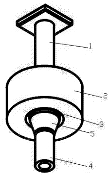
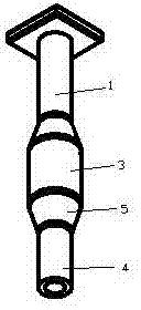
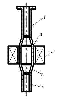
[0015] Electromagnetic swirl nozzle for continuous casting of the present invention, such as figure 1 , image 3 As shown, it includes a nozzle pipe and an electromagnetic swirl device 2, and the electromagnetic swirl device is installed around the middle area 3 of the nozzle pipe. like image 3 As shown, the nozzle pipe is a different diameter structure, including the upper part of the nozzle pipe 1, the middle area of ​​the nozzle pipe 3, the transition section 5 and the molten steel outlet 4, and the middle area of ​​the nozzle pipe is connected to the upper part of the nozzle pipe and the molten steel outlet through the transition section respectively. The cross-sectional area of ​​the middle area of ​​the nozzle pipe is 5 times of the cross-sectional area of ​​the molten steel outlet. The length of the middle area 3 of the nozzle pipe is 40% of the overall le...


PUM


Abstract

The invention relates to an electromagnetic rotational flow water gap for continuous casting. The electromagnetic rotational flow water gap for continuous casting comprises a water gap pipe and an electromagnetic rotational flow device, wherein the electromagnetic rotational flow device is arranged around the middle area of the water gap pipe; the water gap pipe in a different-diameter structure comprises an upper part of the water gap pipe, the middle area of the water gap pipe and a molten steel outlet part; the sectional area of the middle area of the water gap pipe is 1.1-20 times the sectional area of the molten steel outlet part; the length of the middle area of the water gap pipe is 10-90% of the whole length of the water gap pipe; and the cross section of the middle area of the water gap pipe is a round, an oblong, a rectangle and a polygon with 1-20 sides. By enlarging the sectional area of the middle area of the water gap pipe, the electromagnetic rotational flow water gap for continuous casting adds the functional area of a magnetic field to the molten steel, increases a distance between magnetic poles of an externally arranged electromagnetic rotational flow device and improves efficiency of the magnetic field. The electromagnetic rotational flow water gap for continuous casting enables the molten steel in the water gap pipe to generate a relatively strong rotary force, solves bias flow phenomenon of the molten steel in the water gap pipe efficiently and is good for improving quality of steel billets.

Description

technical field [0001] The invention belongs to the technical field of iron and steel smelting equipment, and relates to a continuous casting nozzle, in particular to an electromagnetic swirling nozzle for continuous casting. technical background [0002] In the continuous casting process of steel, the molten steel in the tundish needs to be injected into the crystallizer through the nozzle pipe, and the molten steel is gradually cooled through the crystallizer to form a billet. When the molten steel is injected into the mold through the nozzle pipe, due to partial flow and other reasons, the mold slag on the surface of the molten steel in the mold is easily involved in the molten steel, which affects the quality of the billet. In recent years, a mechanical swirl nozzle has been developed abroad. Due to the short life of the mechanical swirl blades in the nozzle tube under the impact of high-temperature molten steel, it cannot meet the needs of industrial production. Invent...

Claims


Application Information

Patent Timeline
IPC IPC(8): B22D41/62
Inventor 张殿彬
Owner HEBEI SANFANG ELECTRICAL EQUIP
Learn More