
LED light source structure with high illuminating power and improved heat dissipating characteristics

A technology of LED light source and structure, applied in the direction of light source, point light source, slender light source, etc., can solve problems such as the decline of heat dissipation effect, achieve the effect of stable resistance, solve the sharp rise in temperature, and prevent voltage drop

Inactive Publication Date: 2013-06-12
BKTECH
View PDF10 Cites 1 Cited by
  • Summary
  • Abstract
  • Description
  • Claims
  • Application Information

AI Technical Summary

Problems solved by technology

However, in this method, heat is transferred to the heat sink through the insulator formed on the LED chip or the plug-in itself, and the solder layer connecting the LED chip and the heat sink, so there is still a limitation that the heat dissipation effect is reduced.

Method used


Image

  • LED light source structure with high illuminating power and improved heat dissipating characteristics
  • LED light source structure with high illuminating power and improved heat dissipating characteristics
  • LED light source structure with high illuminating power and improved heat dissipating characteristics

Examples


no. 1 example

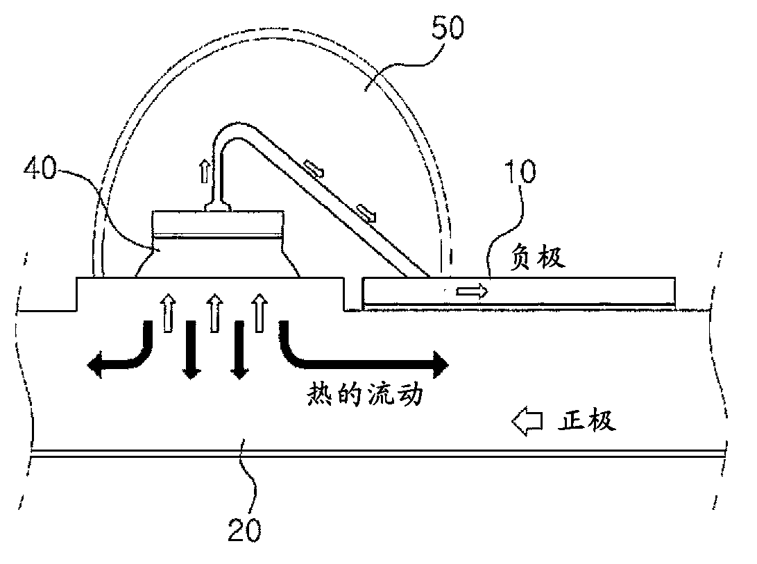
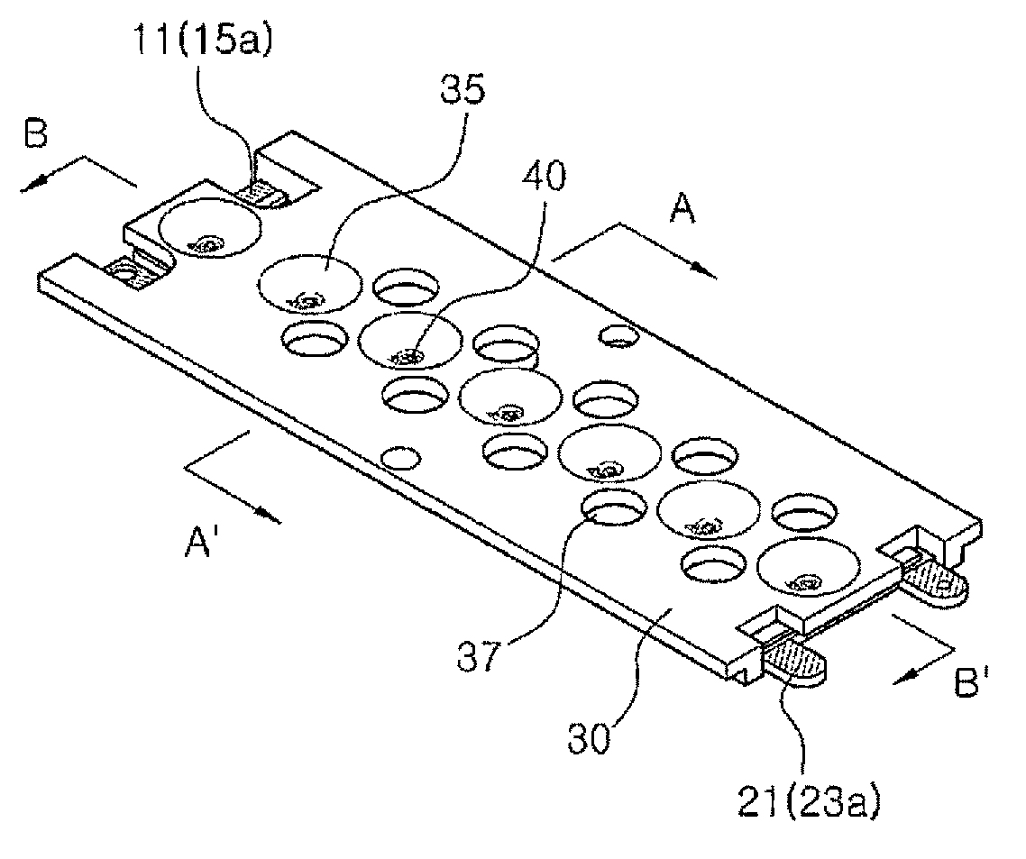
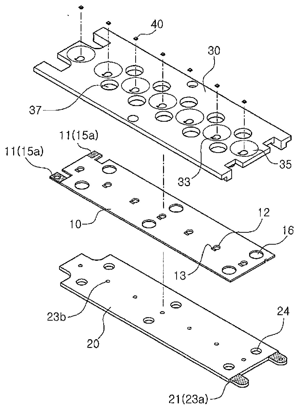
[0060] figure 1 is a conceptual diagram illustrating the structure of an LED light source structure with improved heat dissipation characteristics according to a first embodiment of the present invention, figure 2 is a perspective view illustrating the configuration of the LED light source structure according to the first embodiment, image 3 is an exploded perspective view illustrating the configuration of the LED light source structure according to the first embodiment, Figure 4 is according to image 3 The sectional view of the A-A' line, Figure 5 is according to image 3 The sectional view of the B-B' line, Figure 6 is a perspective view illustrating a state in which a plurality of LED light source structures according to the first embodiment are combined.

[0061] As shown in the figure, the LED light source structure according to the present invention includes: a first electrode unit 10 and a second electrode unit 20 made of a metal body with excellent electrica...

no. 2 example

[0091] The second embodiment of the high-luminosity LED light source structure with improved heat dissipation characteristics of the present invention will be described below. In this embodiment, the same reference numerals are used for constituent elements corresponding to those of the first embodiment.

[0092] Figure 7 is a cross-sectional view illustrating an LED light source structure according to a second embodiment of the present invention, and is illustrated in accordance with image 3 The A-A' line in the figure cuts the deformation form of the cut surface after the LED light source structure is cut.

[0093] As shown in the figure, in this embodiment, in order to increase the mounting height of the LED chip 40 and improve light output, a second electrode portion 26 protruding toward the through hole 12 is formed on the second electrode unit 20 . At this time, the second electrode part 26 can be formed as the protrusion by using a plate material with protrusions as...

no. 3 example

[0100] Figure 8 is a perspective view of an LED light source structure according to a third embodiment of the present invention, Figure 9 is a side view of an LED light source structure according to a third embodiment of the present invention, Figure 10 is an exploded perspective view of an LED light source structure according to a third embodiment of the present invention, Figure 11 is a side sectional view of an LED light source structure according to a third embodiment of the present invention, Figure 12 is a top view of the LED light source structure according to the third embodiment of the present invention.

[0101] Such as Figure 8 to Figure 12 As shown, in the fourth embodiment of the high-luminosity LED light source structure with improved heat dissipation characteristics according to the present invention, the metal body with excellent electrical and thermal conductivity, that is, the second electrode unit 20 is formed to have the shape of a heat sink 60, an...


PUM


Abstract

The present invention relates to an LED light source structure, and more particularly, to an LED light source structure with high illuminating power and improved heat dissipating characteristics, in which metal having superior electric conductivity and thermal conductivity is processed into positive electrode units, and heat generated from an LED chip is directly dissipated through the electrode unit which is used as a positive electrode from among the positive electrode units, thereby improving heat dissipating characteristics, stabilizing a light source and preventing voltage drop, thus enabling output of high illuminating power. The LED light source structure with high illuminating power and improved heat dissipating characteristics is configured in that the LED chip is arranged and heat generated when the LED chip is turned on is dissipated to the outside, wherein the LED light source structure comprises: a first electrode unit (10) made of an electrically conductive material; a second electrode unit (20) made of an electrically conductive and thermally conductive material and electrically insulated from the first electrode unit (10); and an LED chip (40) arranged to use the first electrode unit (10) and the second electrode unit (20) as a positive electrode, wherein the first electrode unit (10) and the second electrode unit (20) are arranged to be brought into surface-contact with the LED chip (40), thus enabling heat generated from the LED chip (40) to be directly conducted and dissipated into the atmosphere.

Description

technical field [0001] The present invention relates to an LED light source structure, in particular to processing a metal with excellent electrical conductivity and thermal conductivity to produce two electrode units, using one of the electrode units to directly discharge the heat generated in the LED chip through the electrode unit to improve heat dissipation characteristics, and A high-luminance LED light source structure with improved heat dissipation characteristics that can output high luminosity by stabilizing the light source and preventing voltage drop. Background technique [0002] LED (Light Emitting Diode, Light Emitting Diode) is a semiconductor element that emits light when a voltage is applied in the forward direction. When a voltage is applied to the LED, the energy of electrons is converted into light energy at the PN junction of the LED to emit light. [0003] This kind of LED can emit light of various colors according to semiconductor materials, has a fast...

Claims


Application Information

Patent Timeline
Patent Type & Authority Applications(China)
IPC IPC(8): F21V29/00F21Y101/02
CPCF21K9/00H05K1/0204H05K1/05H05K2201/09054H05K2201/10106H01L33/60H01L33/62H01L33/647H01L2224/48091H01L2224/48465H01L2224/73265F21V29/767F21Y2103/10F21Y2115/10H01L2924/00014H01L2924/00
Inventor 李东雨
Owner BKTECH
Learn More