
Polycrystalline silicon reduction furnace lining coating and production method thereof

A manufacturing method and reduction furnace technology, which can be applied to manufacturing tools, glass manufacturing equipment, glass cutting devices, etc., and can solve problems such as reducing production costs

Active Publication Date: 2012-09-19
胡倾宇
View PDF2 Cites 7 Cited by
  • Summary
  • Abstract
  • Description
  • Claims
  • Application Information

AI Technical Summary

Problems solved by technology

Conducive to saving energy consumption and thus reducing production costs

Method used


Image

  • Polycrystalline silicon reduction furnace lining coating and production method thereof
  • Polycrystalline silicon reduction furnace lining coating and production method thereof
  • Polycrystalline silicon reduction furnace lining coating and production method thereof

Examples


example 1

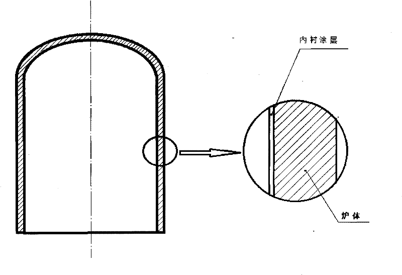
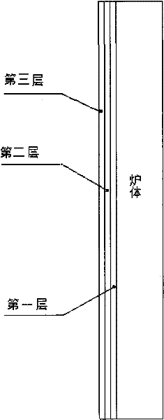
[0021] Example 1: The inner wall of the reduction furnace is mechanically polished, cleaned with organic solvents and pure water, dried and then plated. The system is evacuated, and after reaching the predetermined vacuum degree (10 -4 Pa or so), use an infrared heating element to heat the furnace wall to 300-600°C for baking and degassing. After the degassing is completed, the inner wall of the reduction furnace is cleaned by ion glow discharge with argon gas. Using multi-arc ion plating technology, the furnace wall is the workpiece to be plated (negative potential relative to the multi-arc target), and the temperature of the inner wall of the reduction furnace is controlled at about 300-500°C. First, a layer of pure titanium with a thickness of 0.1-0.5 microns is prepared, and then Nitrogen, grow a layer of 1-10 micron TiN x layer, slowly cooled to room temperature, and the lining coating is prepared.

example 2

[0022] Example 2: The inner wall of the reduction furnace is mechanically polished, washed with organic solvents and pure water, dried and then plated. The system is evacuated, and after reaching the predetermined vacuum degree (10 -4 Pa around), using an infrared heating element to heat the inner wall of the reduction furnace to 300-500°C for baking and degassing. After the degassing is completed, argon gas is passed to perform glow discharge cleaning on the inner wall of the reduction furnace. Using the magnetron sputtering method, the furnace wall is the workpiece to be plated (positive potential relative to the sputtering target), deposit a layer of 0.1-0.5 micron thick pure titanium layer at an ambient temperature of 300-500 ° C, and then grow a layer of nitrogen gas 1-10 micron TiN x layer, slowly cooled to room temperature, and the lining coating is prepared.

example 3

[0023]Example 3: The inner wall of the reduction furnace is mechanically polished, washed with organic solvents and pure water, dried and then plated. The system is vacuumed and the inner wall of the reduction furnace is heated to 300-500°C, and baked for 15 hours to remove the water vapor and other impurity gases adsorbed on the furnace wall. TiCl 4 and ammonia NH 3 Reactive gas, deposition of titanium nitride TiN at a temperature of 400-500°C x After stopping the coating, slowly cool the furnace body to room temperature, and the lining coating is prepared.

[0024] According to the methods of the above embodiments, the lining coating of the reduction furnace can be produced, and the performance test also meets the relevant technical indicators, and also possesses the above-mentioned superiority and significant technical and economic effects compared with the prior art. .


PUM


Abstract

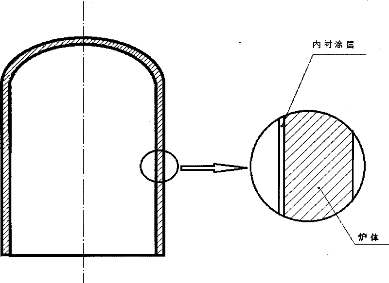
The invention relates to a coating for a furnace wall on the internal side of the furnace body of a polycrystalline silicon reduction furnace (a lining coating for short) and a production method of the coating, in particular to a lining anticorrosive infrared reflection coating of an improved-Siemens-process polycrystalline silicon reduction furnace. The coating is made of a metal-ceramic material. The coating is directly coated on the furnace wall on the internal side of the furnace body of the improved-Siemens-process polycrystalline silicon reduction furnace. The adopted coating method is a physical vapor deposition method or a chemical vapor deposition method. The thickness of the lining coating of the polycrystalline silicon reduction furnace is 1-10 micrometers, the production cost is low and the adhesive force of the coating on the furnace wall is strong. The coating can resist high temperature, strong acid and alkali corrosion and mechanical impact and scraping, the infrared reflection efficiency is high, the service life is long and the loss of heat in the improved-Siemens-process polycrystalline silicon reduction furnace because of heat transfer towards the outside of the furnace can be effectively reduced. Since the coating replaces a pure-gold infrared reflection coating, the expense of the coating material is greatly decreased and the cost of producing polycrystalline silicon products by adopting an improved Siemens process can be greatly decreased.

Description

(1) Technical field [0001] The invention relates to a furnace wall coating (hereinafter referred to as lining coating) for polysilicon reduction furnace body inner side and a preparation method thereof, in particular to the manufacture of silicon semiconductor materials and silicon solar cell materials. (2) Background technology [0002] High-purity polysilicon is the basic raw material for the electronics industry and solar photovoltaic industry. In the next 50 years, it is impossible to replace silicon with other materials and become the main raw material for the electronics and photovoltaic industries. With the rapid development of information technology and solar energy industry, the global demand for polysilicon has grown rapidly, and the price of polysilicon has also skyrocketed. Since 2006, under the influence of the market, my country has set off an upsurge in the construction of polysilicon projects, and the scale and investment are the highest in the world. my cou...

Claims


Application Information

Patent Timeline
IPC IPC(8): C03B33/03
Inventor 胡倾宇
Owner 胡倾宇
Learn More