
Manufacturing method of Foil type strain gauge

A manufacturing method and strain gage technology, applied in the direction of reducing undesired effects, etc., can solve the problems of backward production process, scattered return to zero, uneven thickness, etc., to avoid the difficulty of processing, improve the consistency of return to zero, The effect of improving bond strength

Active Publication Date: 2015-06-10
ZHONGHANG ELECTRONICS MEASURING INSTR
View PDF5 Cites 0 Cited by
  • Summary
  • Abstract
  • Description
  • Claims
  • Application Information

AI Technical Summary

Problems solved by technology

The disadvantages of this method are: the production process is backward, the efficiency is low, the thickness of the substrate is difficult to control, the thickness of each substrate in the same batch is uneven, the thickness deviation between different batches is relatively large, and some maximum deviations more than 30%
The strain gauges produced by this method are prone to creep, return to zero scattered and unstable, and are sensitive to humidity and temperature changes, which may easily cause changes in the resistance of the strain gauge and zero signal; the substrate is relatively brittle and easy to break

Method used


Image

  • Manufacturing method of Foil type strain gauge
  • Manufacturing method of Foil type strain gauge
  • Manufacturing method of Foil type strain gauge

Examples


Embodiment Construction

[0010] The present invention will be further described below in conjunction with the embodiments and accompanying drawings.

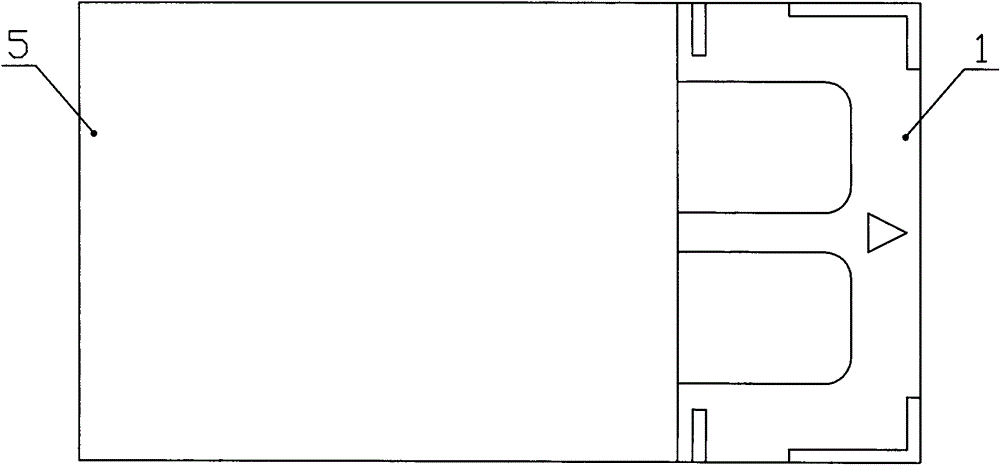
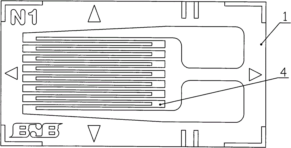
[0011] like Figure 1-3 As shown, the foil strain gauge includes a base and a sensitive grid. The base is any polymer engineering plastic film among polyimide film, polyether ether ketone film, polyphenylene sulfide film, and polyester film. One of its surfaces After treatment, a treated surface 2 capable of being strongly combined with the adhesive layer 3 is formed; the sensitive grid 4 is firmly attached to the film substrate 1 with the treated surface 2 through the adhesive layer 3 of epoxy resin or phenolic-epoxy resin; There is a sealing layer 5 on the surface of the sensitive grid 4, the material of the sealing layer 5 is the same as that of the film substrate 1, and it is firmly attached to the sensitive grid 4 through the adhesive layer 3.

[0012] The manufacture method of foil strain gauge of the present invention is:

[0013] One surface o...


PUM


Abstract

The invention discloses a foil type strain gauge and a manufacturing method thereof. A macromolecular engineering plastic film is served as a substrate; a sensitive grid is firmly glued to a film substrate layer through a gluing layer; and a sealing layer is arranged on the surface of the sensitive grid. The manufacturing method comprises the following steps: performing plasma or corona treatment on one surface of the film substrate and then treating the surface by using a coupling reagent; coating epoxy resin or phenolic aldehyde-epoxy resin on the surface of the film substrate or one surface of a sensitive grid blank; gluing and curing the film substrate and the sensitive grid blank; processing the sensitive grid blank into the sensitive grid; and lastly, gluing the sealing layer on the surface of the sensitive grid. According to the manufacturing method provided by the invention, the problems of the substrate of high difficulty in processing, unequal and uneven thickness, and the like, are solved, and the working efficiency is increased; the peel strength between the sensitive grid and the substrate is increased; the sealing layer has an excellent function for protecting the sensitive grid; and various aspects of the strain gauge, such as moisture and thermal resistance, creep deformation, resetting consistency, and the like, are obviously improved.

Description

technical field [0001] The invention relates to a strain gauge and a manufacturing method thereof, in particular to a foil strain gauge and a manufacturing method thereof. Background technique [0002] At present, the known foil-type resistance strain gauge is to directly coat the polymer liquid resin insulating material on the surface of the rolled-formed metal foil, form a polymer insulating substrate after drying, and then use photolithography and etching on the metal foil. The technology makes the metal foil material form a sensitive grid, and then forms a welding terminal at the rear end of the sensitive grid. The defects of this method are: the production process is backward, the efficiency is low, the thickness of the substrate is difficult to control, the thickness of each substrate in the same batch is uneven, the thickness deviation between different batches is relatively large, and some maximum deviation More than 30%. The strain gauge produced by this method is...

Claims


Application Information

Patent Timeline
Patent Type & Authority Patents(China)
IPC IPC(8): G01D3/028
Inventor 晏志鹏张勋刘鹏赵家辉任博哲赵凯锋
Owner ZHONGHANG ELECTRONICS MEASURING INSTR
Learn More