
Machining process for zirconium alloy

A processing technology, zirconium alloy technology, applied in the field of alloys, can solve the problems of reduced corrosion resistance, poor plastic processing ability of zirconium alloys, large second phase particle size, etc., to improve plastic processing ability, improve plastic deformation ability, save Effects of Time and Energy Consumption

Inactive Publication Date: 2012-09-12
CHONGQING UNIV
View PDF1 Cites 15 Cited by
  • Summary
  • Abstract
  • Description
  • Claims
  • Application Information

AI Technical Summary

Problems solved by technology

[0004] However, the cooling rate of the core of the large-sized ingot is insufficient after the β-phase quenching process, and precipitates are inevitably generated at the α-phase boundary. The precipitates in the existing zirconium alloy processing technology are distributed in bands, and in the The uneven growth of the α-phase hot rolling process during the heat preservation process leads to the inability to disperse the second phase particles in the zirconium alloy, resulting in poor plastic deformation ability of the zirconium alloy and poor plastic processing ability of the zirconium alloy
[0005] In addition, the precipitated phase is distributed in a band shape and grows unevenly during the heat preservation process of the α-phase hot rolling process, resulting in a larger particle size of the second phase in the zirconium alloy and unable to disperse the distribution, resulting in a core structure made of zirconium alloy. Corrosion resistance of materials decreases in nuclear reactors

Method used


Image

  • Machining process for zirconium alloy
  • Machining process for zirconium alloy
  • Machining process for zirconium alloy

Examples


Embodiment 1

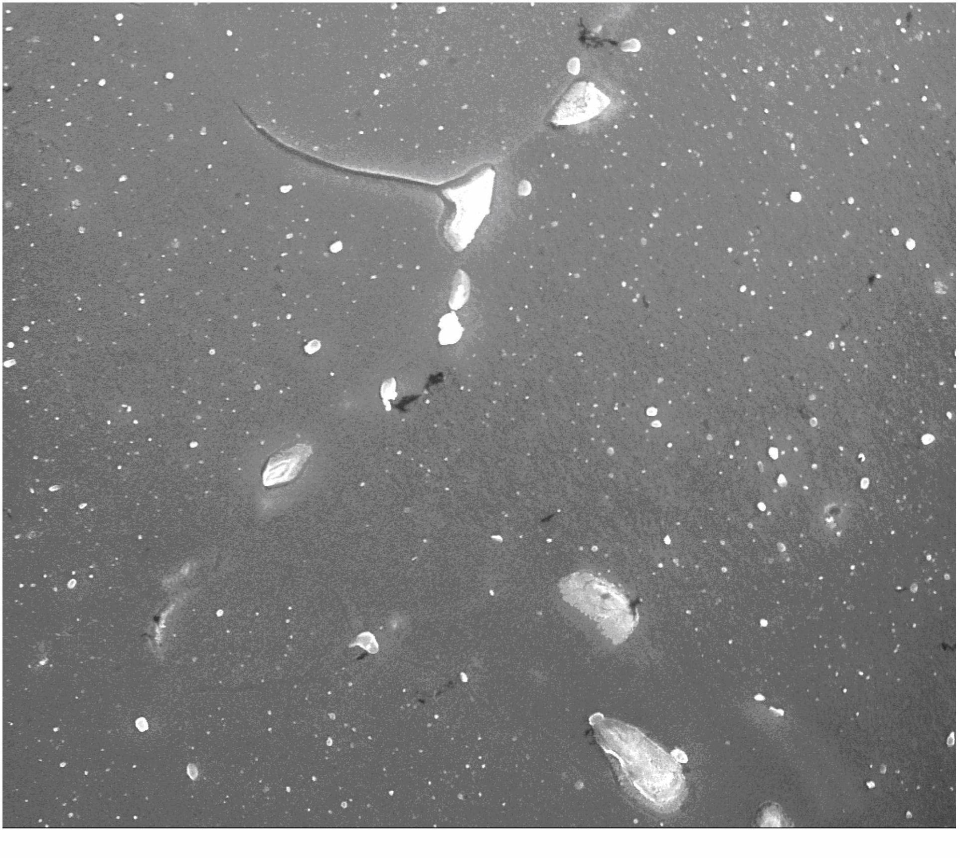
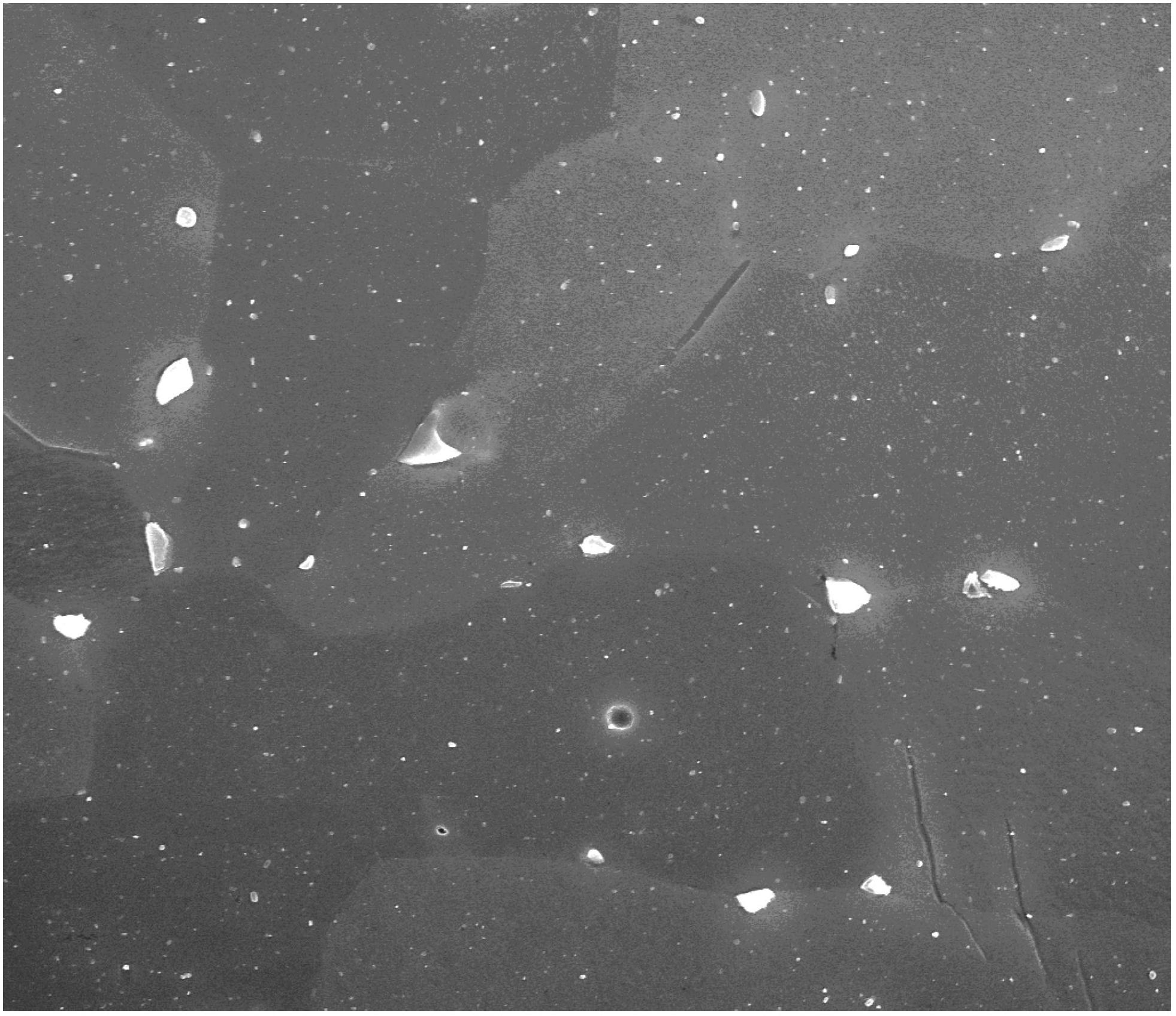
[0054] Taking a zirconium alloy with a weight percentage of 1% of the Sn element and a 0.3% weight percentage of the Nb element as an example, it is processed by the existing processing technology under the conditions of a vacuum degree of 2.27E-3Pa and an acceleration voltage of 20.00KV. The scanning electron microscope image obtained is figure 2 As shown, among them, the larger bright spot is the precipitated phase produced at the grain boundary, which is prone to cracks and is harmful to the subsequent processing performance. Obviously, the particle size and distribution of the second phase are not uniform, and the size is large; The same zirconium alloy is processed by the process provided by the embodiment of the present invention. In the step annealing process, the pre-annealing step is carried out at 500°C for 0.5h, and the annealing and heat preservation step is carried out at 650°C for 2h. After the processing is completed , the scanning electron microscope image of ...

Embodiment 2

[0056] Taking a zirconium alloy with a weight percentage of Sn element (1%) and a weight percentage of Nb element (0.3%) as an example, it is processed by the existing processing technology, and the scanning electron microscope image obtained under the conditions is as follows figure 2 As shown, among them, the larger bright spot is the precipitated phase produced at the grain boundary, which is prone to cracks and is harmful to the subsequent processing performance. Obviously, figure 2 The larger bright spot in the zirconium alloy is that the size and distribution of the second phase particles in the zirconium alloy are not uniform; the same zirconium alloy is processed by the method provided by the embodiment of the present invention, and the pre-annealing step in the step annealing process is 550 ℃ temperature for 1h, and the annealing and heat preservation step was carried out at 550℃ for 2h. The scanning electron microscope image obtained by using the same scanning equip...

Embodiment 3

[0058] Taking a zirconium alloy with a weight percent of Sn element of 0.8% and a weight percent of Nb element of 0.35% as an example, it is processed by the existing processing technology, and the scanning electron microscope image obtained under the conditions is as follows Figure 5 As shown, among them, the larger bright spot is the precipitated phase produced at the grain boundary, which is prone to cracks and is harmful to the subsequent processing performance. Obviously, Figure 5 The larger bright spot in the zirconium alloy is that the size and distribution of the second phase particles in the zirconium alloy are not uniform; the same zirconium alloy is processed by the method provided by the embodiment of the present invention, and the pre-annealing step in the step annealing process is 550 ℃ for 2 hours, and the annealing and heat preservation step was carried out at 650 ℃ for 2 hours. The scanning electron microscope image obtained by using the same scanning equipme...


PUM


Abstract

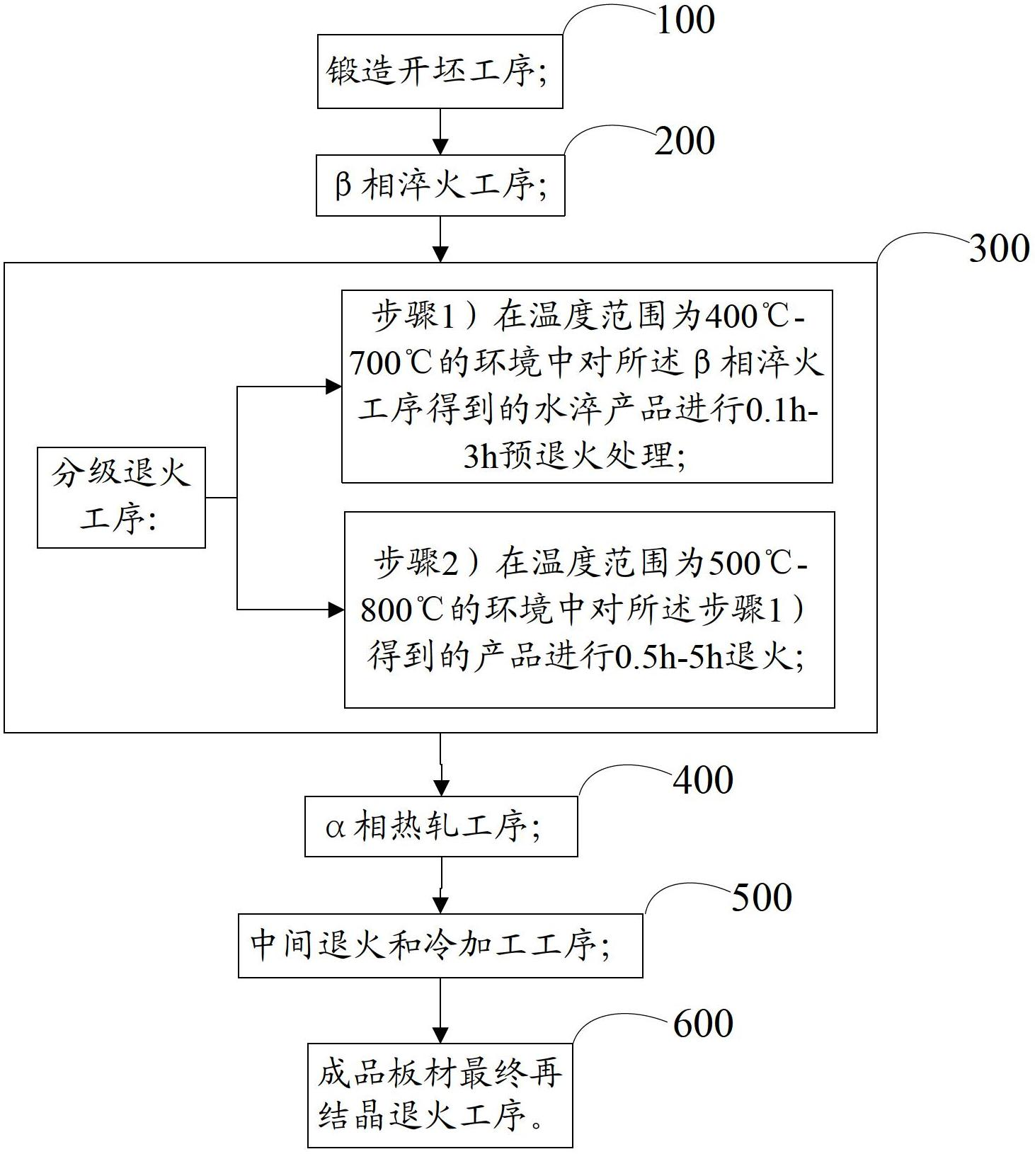
The invention discloses a machining process for a zirconium alloy. The machining processing comprises the following sequential steps of: a hammer cogging working procedure, a beta-phase quenching working procedure, a graded annealing working procedure, an alpha-phase hot rolling working procedure, a middle annealing and cold machining working procedure, and a final finished-product board re-crystallizing and annealing working procedure, wherein the graded annealing working procedure comprises pre-annealing treatment; the re-annealing treatment specifically comprises the following steps of: carrying out the pre-annealing treatment on a water quenched product obtained by the beta-phase quenching working procedure under the environment in a temperature range of 400-700 DEG C for 0.1-3 hours; and carrying out annealing and heat preservation on a product obtained by the pre-annealing treatment under the environment in a temperature range of 500-800 DEG C for 0.5-5 hours. The machining process for the zirconium alloy disclosed by the invention enables second-phase grains in the zirconium alloy to be dispersed and distributed, so as to improve the plastic deformation capability of the zirconium alloy and improve the plastic machining capability of the zirconium alloy; and meanwhile, the machining process for the zirconium alloy further can improve the corrosion resistance of a core structural material prepared by the zirconium alloy in a nuclear reactor.

Description

technical field [0001] The invention relates to the technical field of alloys, in particular to a processing technology for zirconium alloys. Background technique [0002] Zirconium alloy is a non-ferrous alloy composed of zirconium as a matrix and adding other elements. It has good corrosion resistance, moderate mechanical properties and low atomic thermal neutron absorption in high temperature and high pressure water and steam at 300°C-400°C Therefore, zirconium alloys are often used as core structural materials for water-cooled nuclear reactors, such as fuel cladding, pressure tubes, brackets, and tunnel tubes. [0003] The existing zirconium alloy processing technology includes: forging blanking process, β phase quenching process, α phase hot rolling process, intermediate annealing and cold working process, and final recrystallization annealing process of finished plate; among them, the forging blanking process is at 900 In the environment of ℃-1150℃, the as-cast zircon...

Claims


Application Information

Patent Timeline
Patent Type & Authority Applications(China)
IPC IPC(8): C22F1/18C22C16/00
Inventor 栾佰峰柴林江刘庆
Owner CHONGQING UNIV
Learn More