
Automatic gain amplification circuit with inverse exponential characteristic type digital control circuit

A digital control circuit, automatic gain technology, applied in gain control, amplification control, electrical components and other directions to achieve the effect of reducing circuit overhead and power consumption, simple design, and eliminating external components

Active Publication Date: 2012-08-01
杭州中科微电子有限公司
View PDF4 Cites 21 Cited by
  • Summary
  • Abstract
  • Description
  • Claims
  • Application Information

AI Technical Summary

Problems solved by technology

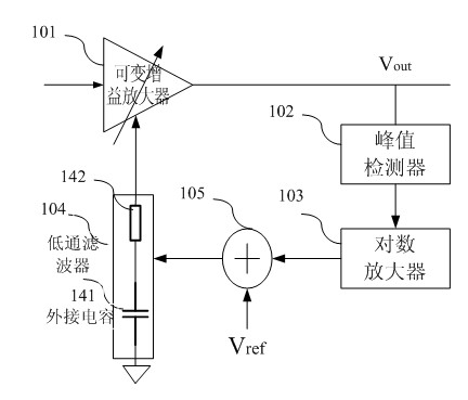
Although the analog control circuit can continuously adjust the gain and realize the seamless connection of each step, it has obvious disadvantages. The continuous adjustment speed is relatively slow, and the charge pump circuit can only be used to increase the adjustment speed.
The title of the prior art paper is "Design and Realization of Low Power Consumption Charge Pump Programmable Gain Amplifier", which increases the speed of adjustment by increasing the current of the charge pump. This implementation method increases the operating current by an order of magnitude, and at the same time increases the ripple on the control voltage, which directly leads to the reduction of the signal-to-noise ratio of the output signal. Therefore, this analog control circuit can only be suitable for gain-adjustable amplifiers that do not require too high time requirements for stable signals.

Method used


Image

  • Automatic gain amplification circuit with inverse exponential characteristic type digital control circuit
  • Automatic gain amplification circuit with inverse exponential characteristic type digital control circuit
  • Automatic gain amplification circuit with inverse exponential characteristic type digital control circuit

Examples


no. 1 example

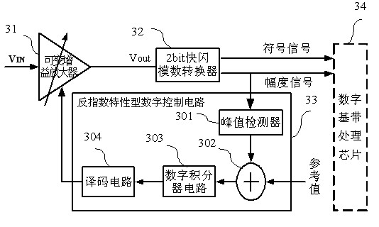
[0073] image 3 A block diagram of the automatic gain large circuit with anti-exponential characteristic digital control circuit of the embodiment of the present invention is given. to combine image 3 Explain the realization structure of the automatic control mode in the present invention, set the value of M to 5. The input signal VIN enters the input terminal of the digital variable gain amplifier 31, and the digital variable gain amplifier is cascaded connection of five stages of variable gain amplifier stages, and the output of the digital variable gain amplifier 31 is connected to the 2bit flash modulus Converter 32, the amplitude signal bit of the 2bit flash analog-to-digital converter 32 is output to the peak detector 301 in the anti-exponential characteristic digital control circuit 33, the output of the peak detector 301 and the reference value provided by the chip pass through the subtractor circuit 302 For comparison, the output of the subtractor circuit 302 is pr...

no. 2 example

[0077] Figure 6 shows the block diagram of the anti-exponential characteristic digital control circuit in the second embodiment of the present invention, and the fourth embodiment combines Figure 6 The control principle of the anti-exponential characteristic digital control circuit is explained in detail. The anti-exponential characteristic type digital control circuit includes a digital integrator circuit 61 , a decoding circuit 62 , a peak detector 63 and a subtractor circuit 64 , wherein the digital integrator circuit 61 is composed of two dichotomy algorithm circuits 65 and 66 . The amplitude signal bit obtained by quantizing the intermediate frequency signal by the 2bit flash analog-to-digital converter is input to the peak detector 63, and the peak detector 63 obtains the amplitude signal of the intermediate frequency signal by processing the number of the largest continuous high level number in the amplitude bit, and obtains The amplitude signal of the intermediate fre...

no. 3 example

[0079] Figure 7 It is a connection block diagram of the automatic gain control amplifier with the anti-exponential characteristic digital control circuit of the radio frequency chip of the embodiment of the present invention and the subsequent digital baseband chip. 71 is an automatic gain control amplifier with an anti-exponential characteristic digital control circuit, and 72 is a chip configured with a baseband processing module. The automatic gain amplifier 71 of the radio frequency chip includes a digital variable gain amplifier 701 , a 2-bit flash analog-to-digital converter 702 and an inverse exponential characteristic digital control circuit 703 . Wherein, the baseband processing module 72 has a digital output detection function, and it can be configured in an external control mode through the receiver to control the automatic gain control amplifier 71, and the signal of the amplified path is sampled by the digital baseband module 72 through the analog-to-digital conv...


PUM


Abstract

The invention discloses an automatic gain amplification circuit with an inverse exponential characteristic type digital control circuit, which is formed by a digital variable gain amplifier, a 2-bit flash analog-to-digital converter of a digital circuit and the inverse exponential characteristic type digital control circuit, wherein the digital variable gain amplifier is formed by cascading a plurality of digital variable gain amplifier stages; the 2-bit flash analog-to-digital converter comprises three comparator circuits, a coding circuit and a fixed reference voltage configuration circuit; and the inverse exponential characteristic type digital control circuit comprises a peak detector, a subtracter circuit, an integrator circuit and a decoding circuit. The inverse exponential characteristic type digital control circuit detects a digital signal output by the 2-bit flash analog-to-digital converter; the detected signal amplitude is compared with a reference value of a reference voltage by the subtracter circuit; and after a comparison result is integrated and decoded, a feedback control signal is output to regulate the gain of the variable gain amplifier PGA (Programmable Gain Amplifier). The automatic gain amplification circuit further comprises a switch for the control circuit, the switching between the inverse exponential characteristic type digital control circuit and an external control circuit can be implemented, and the automatic gain amplification circuit is particularly suitable for a radio frequency front-end circuit with the requirements on few off-chip components and compact structure.

Description

Background technique [0001] In recent years, with the continuous emergence of new technologies in the field of information technology and the continuous progress of technology, the RF front-end and baseband chips of various receiver systems have achieved great development. Highly integrated radio frequency chips and high-speed control schemes are more and more popular. This kind of radio frequency chip requires the least external components, and at the same time needs to automatically control the response speed of the amplifier circuit to the input signal fast enough to keep up with the change of the input signal. . [0002] As we all know, highly integrated radio frequency chips require as few external components as possible. Traditional feedback automatic gain control amplifier circuits require a large capacitor outside the chip to charge and discharge the charge pump. The value of this capacitor is Generally greater than 1n, this determines that such a capacitor cannot be ...

Claims


Application Information

Patent Timeline
IPC IPC(8): H03G3/30
Inventor 何晓丰
Owner 杭州中科微电子有限公司
Learn More