
P-type doubled diffusion metal-oxide-semiconductor (DMOS) device and making method thereof

A device manufacturing method and device technology, applied in semiconductor/solid-state device manufacturing, semiconductor devices, electrical components, etc., can solve problems such as increased on-resistance, increased product cost, and decreased competitiveness, and achieve stable breakdown voltage and reduced Product cost, effect of reducing product area

Inactive Publication Date: 2012-05-23
CSMC TECH FAB1 +1
View PDF6 Cites 3 Cited by
  • Summary
  • Abstract
  • Description
  • Claims
  • Application Information

AI Technical Summary

Problems solved by technology

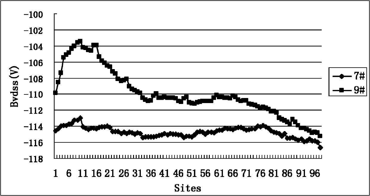
[0003] Compared with N-type DMOS devices, when manufacturing P-type DMOS devices, impurities are easily precipitated on the back of the substrate, and then self-doping is formed on the back of the substrate, which eventually leads to unstable breakdown voltage of the device
[0004] In order to solve the influence of self-doping on the back of the substrate, when manufacturing P-type DMOS devices, a substrate with a higher resistivity is generally selected. However, this will increase the on-resistance per unit area of ​​the product, thereby increasing the product area and resulting in an increase in product cost. , a decrease in competitiveness

Method used


Image

  • P-type doubled diffusion metal-oxide-semiconductor (DMOS) device and making method thereof
  • P-type doubled diffusion metal-oxide-semiconductor (DMOS) device and making method thereof
  • P-type doubled diffusion metal-oxide-semiconductor (DMOS) device and making method thereof

Examples


Embodiment Construction

[0027] In order to make the above objects, features and advantages of the present invention more comprehensible, specific implementations of the present invention will be described in detail below in conjunction with the accompanying drawings.

[0028] In the following description, a lot of specific details are set forth in order to fully understand the present invention, but the present invention can also be implemented in other ways different from those described here, and those skilled in the art can do it without departing from the meaning of the present invention. By analogy, the present invention is therefore not limited to the specific examples disclosed below.

[0029] Secondly, the present invention is described in detail in combination with schematic diagrams. When describing the embodiments of the present invention in detail, for the convenience of explanation, the cross-sectional view showing the device structure will not be partially enlarged according to the gener...


PUM


Abstract

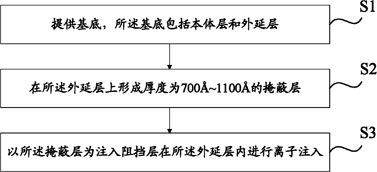
The embodiment of the invention discloses a P-type doubled diffusion metal-oxide-semiconductor (DMOS) device and a making method thereof. The method comprises the following steps of: providing a substrate, wherein the substrate comprises a body layer and an epitaxial layer; forming a masking layer with thickness of 700 to 1,100A on the epitaxial layer; and performing ion implantation in the epitaxial layer by taking the masking layer as an injection barrier layer. The P-type DMOS device comprises the substrate, wherein the substrate comprises the body layer and the epitaxial layer, the epitaxial layer comprises the masking layer and an ion implantation layer, the masking layer is positioned on the epitaxial layer and has the thickness of 700 to 1,100A, and the ion implantation layer is formed by blocking an ion implantation process. With the adoption of the making method of the P-type DMOS device, which is provided by the invention, the problem of auto-doping on the back side of the substrate can be solved under the condition of using the low-resistivity substrate; therefore, the product area can be reduced, the product cost is reduced, and the competitiveness is increased.

Description

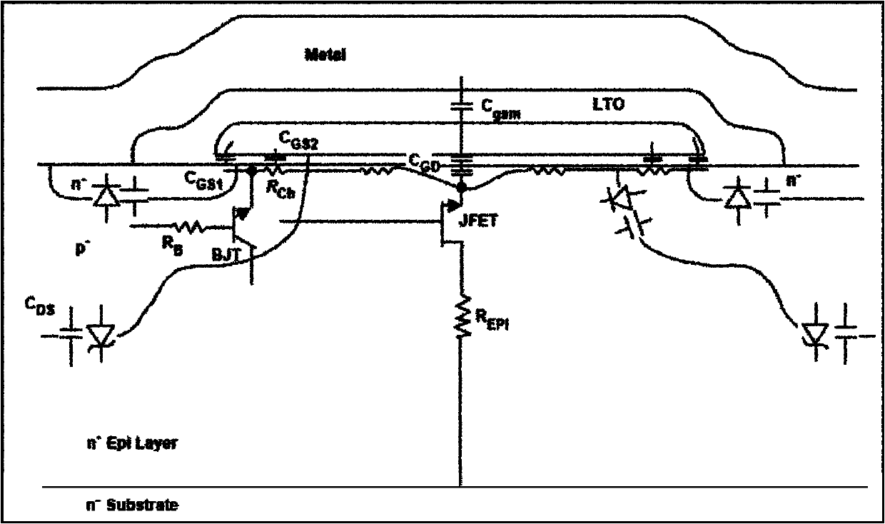
technical field [0001] The invention relates to the technical field of semiconductor manufacturing, and more specifically, to a P-type DMOS device and a manufacturing method thereof. Background technique [0002] DMOS devices can be divided into N-type DMOS and P-type DMOS according to the different ions implanted into JFET. N-type DMOS is generally implanted with arsenic As or antimony Sb in the epitaxial layer, and P-type DMOS is generally implanted with boron B. see figure 1 , which shows a parasitic field effect transistor JFET formed in the epitaxial layer between 2 wells of a DMOS device. JFET implantation generally implants the same ions as the doping elements of the epitaxial layer into the surface of the epitaxial layer, and then adopts a push-in process to drive the implanted ions into a certain depth in the epitaxial layer. The JFET injection has a great influence on the on-resistance and the breakdown voltage of the DMOS device. [0003] Compared with N-type D...

Claims


Application Information

Patent Timeline
Patent Type & Authority Applications(China)
IPC IPC(8): H01L21/336H01L29/78H01L29/06
Inventor 赵秋森邓小社
Owner CSMC TECH FAB1
Learn More