Metal/nano metal based solid glucose electrode and its preparation method
A nano-metal and metal nano-technology, applied in the field of electrochemical detection, can solve the problems that the sensitivity and life of conductive polymer biosensors cannot meet the needs of actual use, biosensors cannot, and limit the scope of application, etc., to achieve long service life and detection The effect of low lower limit and compact size
- Summary
- Abstract
- Description
- Claims
- Application Information
AI Technical Summary
Problems solved by technology
Method used
Image
Examples
preparation example Construction
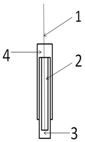
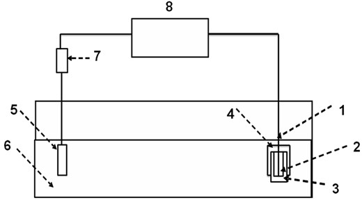
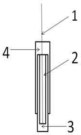
[0026] The steps of the preparation method of the metal / nanometal-based solid glucose electrode are as follows:
[0027] 1) For the first metal wire 1 with a length of 5-15 cm, first remove the surface oil stains with acetone solution, then wash with 1-2M dilute hydrochloric acid or dilute nitric acid to remove oxides, rinse with deionized water and then dry;
[0028] 2) The positive pole or negative pole of the output voltage of the function signal generator 8 is connected to the negative pole or positive pole of the diode 7, and the other pole of the diode 7 is connected to the signal channel of the oscilloscope. Adjust the function signal generator 8, observe the oscilloscope graph, and obtain The power supply is a half-sine wave carrier DC power supply with a peak value of 450-800mV and a frequency of 50HZ;
[0029] 3) Connect one end of the first wire 1 to the negative electrode of the output voltage of the function signal generator 8 through a wire, connect one end of th...
Embodiment 1
[0035] 1) The surface of the first metal wire 1 with a length of 5 cm is polished with corundum powder, then washed with 1M dilute hydrochloric acid or dilute nitric acid, rinsed with deionized water and dried;
[0036] 2) Adjust the function signal generator 8 (Rite Electronics SG1005A) to generate a sine wave function signal with a peak value of 600 mV and a frequency of 50Hz; then connect the negative pole of the output voltage of the function signal generator 8 (Rite Electronics SG1005A) with the The cathode of diode 7 (Schottky diode MBR1045) is connected to the cathode, and the anode of diode 7 (Schottky diode MBR1045) is connected to the signal channel of the oscilloscope (Tektronix TDS1002). Observe the oscilloscope graph and show that the obtained power supply is 450mV in peak value. Half-sine wave carrier DC power supply with a frequency of 50HZ;
[0037] 3) Connect one end of the polished and cleaned first wire 1 to the anode of the diode 7 (Schottky diode MBR1045) ...
Embodiment 2
[0042] 1) The surface of the first metal wire 1 with a length of 15 cm is polished with corundum powder, then washed with 2M dilute hydrochloric acid or dilute nitric acid, rinsed with deionized water and dried;
[0043] 2) Adjust the function signal generator 8 (Rite Electronics SG1005A) to generate a sine wave function signal with a peak value of 1000mV and a frequency of 50Hz; then output the voltage at the positive pole and diode of the function signal generator 8 (Rite Electronics SG1005A). The anode of 7 (Schottky diode MBR1045) is connected, and the cathode of diode 7 (Schottky diode MBR1045) is connected with the signal channel of the oscilloscope (Tektronix TDS1002). It is a half-sine wave carrier DC power supply of 50HZ;
[0044] 3) Connect one end of the polished and cleaned first wire 1 to the negative electrode of the output voltage of the function signal generator 8 (Rite Electronics SG1005A) through a wire, and connect one end of the second wire 5 to the diode 7...
PUM
| Property | Measurement | Unit |
|---|---|---|
| length | aaaaa | aaaaa |
| length | aaaaa | aaaaa |
| length | aaaaa | aaaaa |
Abstract
Description
Claims
Application Information
 - R&D Engineer
- R&D Manager
- IP Professional
- Industry Leading Data Capabilities
- Powerful AI technology
- Patent DNA Extraction
Browse by: Latest US Patents, China's latest patents, Technical Efficacy Thesaurus, Application Domain, Technology Topic, Popular Technical Reports.
© 2024 PatSnap. All rights reserved.Legal|Privacy policy|Modern Slavery Act Transparency Statement|Sitemap|About US| Contact US: help@patsnap.com


