Metal diffusion barrier layer between flexible metal substrate and back electrode of solar battery and fabrication method thereof

A technology of solar cells and metal diffusion, applied in the direction of circuits, electrical components, climate sustainability, etc., can solve the problems of high cost, shedding manufacturing cost, cracking of the solar cell barrier layer, etc., to achieve high bonding force, low cost production, high The effect of efficient production

Inactive Publication Date: 2011-09-28
XIANGTAN UNIV
View PDF4 Cites 14 Cited by
  • Summary
  • Abstract
  • Description
  • Claims
  • Application Information

AI Technical Summary

Problems solved by technology

[0010] The purpose of the present invention is to provide a multi-layer metal diffusion barrier that can be prepared at low cost and has high binding force for the problems of cracking, shedding and high manufacturing cost of the existing flexible metal substrate CIGS thin film solar cell barrier layer. its preparation method

Method used


Image

  • Metal diffusion barrier layer between flexible metal substrate and back electrode of solar battery and fabrication method thereof
  • Metal diffusion barrier layer between flexible metal substrate and back electrode of solar battery and fabrication method thereof
  • Metal diffusion barrier layer between flexible metal substrate and back electrode of solar battery and fabrication method thereof

Examples


Embodiment 1

[0049] Use copper tape as the substrate

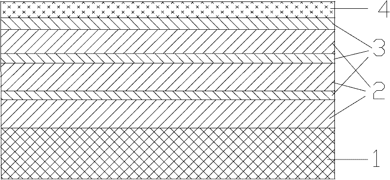
[0050] Put the copper strip on the continuous electroplating production line, and go through degreasing-activation-nickel plating-nickel-molybdenum alloy plating-nickel plating-nickel-molybdenum alloy plating-nickel plating-nickel-molybdenum alloy plating. Then, the plated strip is rapidly heat-treated in a protective atmosphere. The total thickness of the coating is 8 microns, the total number of layers is 16 layers, the thickness of each nickel coating is 0.8 microns, and the thickness of each nickel-molybdenum alloy coating is 0.2 microns.

[0051] Degreasing conditions:

[0052] Sodium hydroxide 30g / L, sodium carbonate 40g / L, sodium phosphate 30g / L, sodium silicate 8g / L, oil removal temperature: 80°C.

[0053] Activation conditions:

[0054] Sulfuric acid: 40g / L, activation temperature: room temperature.

[0055] Nickel plating conditions: Ultrasonic direct current electroplating

[0056] Nickel sulfate 280g / L, nickel chloride...

Embodiment 2

[0062] The stainless steel strip is selected as the substrate, and it undergoes pre-plating pretreatment—nickel plating—nickel-molybdenum alloy plating—nickel plating—nickel-molybdenum alloy plating—nickel plating—nickel-molybdenum alloy plating. Then, the plated strip is rapidly heat-treated in a protective atmosphere. The total thickness of the coating is 9 microns, the total number of layers is 12 layers, the thickness of each nickel coating is 1 micron, and the thickness of each nickel-molybdenum alloy coating is 0.5 micron.

[0063] Wherein the conditions of nickel plating, nickel-molybdenum alloy plating and the conditions of rapid heat treatment are the same as in Example 1.

[0064] Pre-plating pretreatment is conventional stainless steel pre-plating pretreatment.


PUM

PropertyMeasurementUnit
thicknessaaaaaaaaaa
thicknessaaaaaaaaaa
thicknessaaaaaaaaaa

Abstract

The invention discloses a metal diffusion barrier layer between a flexible metal substrate and a back electrode of a solar battery, and a preparation method thereof. According to the invention, nickel coating layers and nickel-molybdenum alloy coating layers are alternately plated on a flexible metal substrate, and then subjected to rapid heat treatment to obtain a multi-layer coating of a laminar structure to serve as a diffusion barrier layer, wherein the nickel coating layers are directly connected with the metal substrate; and the nickel-molybdenum alloy coating layers are connected with the back electrode. Based on material selection and the design of the multi-layer laminar structure, the coating layers can effectively barrier the diffusion of substrate elements to a battery body, and no new harmful element is introduced. Meanwhile, the metal diffusion barrier layer has a higher bonding force with the substrate and the back electrode, and can be manufactured with low cost and high efficiency in the continuous electroplating manner.

Description

technical field [0001] The invention relates to a metal diffusion barrier between a flexible metal substrate and a back electrode of a solar cell and a preparation method thereof, in particular to a method for preparing a multilayer metal coating on a flexible metal substrate as a CIGS solar cell diffusion barrier. Background technique [0002] A solar cell is a device that converts light energy into electrical energy. Among them, thin-film solar cells with a chalcopyrite phase (including solar cells such as copper indium selenide, copper indium sulfur, and copper indium gallium selenide, hereinafter referred to as CIGS) have stable performance, Strong anti-radiation ability, its photoelectric conversion efficiency is currently the first among all kinds of thin film solar cells, wide spectral response range, and the output power is higher than any other type of solar cells under the light intensity of rainy days, it is known internationally as the most promising solar cell in...

Claims


Application Information

Patent Timeline
Patent Type & Authority Applications(China)
IPC IPC(8): C25D5/12H01L31/02C25D3/56C25D3/12H01L31/18
CPCY02P70/50
Inventor 潘勇范清喜周兆锋周杰陈浩李凯
Owner XIANGTAN UNIV
Why Eureka
Try Eureka