


Quick Research
Generate reliable direction feasibility study reports for your R&D in just a few steps.

Technical Q&A
Discover and master advanced knowledge NOW. Basics, ideas, possibilities, all at once.

Find Solutions
As an expert in R&D theories, this can generate solutions to your technical problems instantly.

Evaluate Feasibility
Analyze your overall solution with one click, know your potential R&D risks in advance.

Monitor Landscape
Get weekly tech updates, stay abreast of the latest tech innovations and key insights.
Production process of steel slag micro-powder
A production process, steel slag micropowder technology, applied in the field of steel slag micropowder production technology, can solve the problems of large equipment investment, large floor area, complex process, etc., and achieve the effects of reduced investment, safe operation and simple process
- Summary
- Abstract
- Description
- Claims
- Application Information
AI Technical Summary
Problems solved by technology
Method used
Image

Examples
Embodiment 1
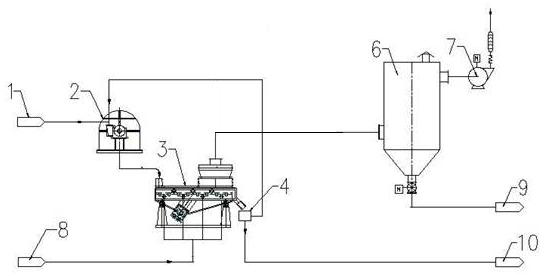
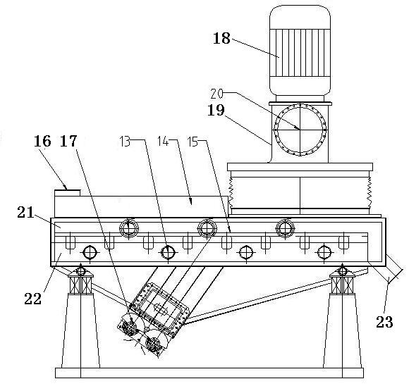
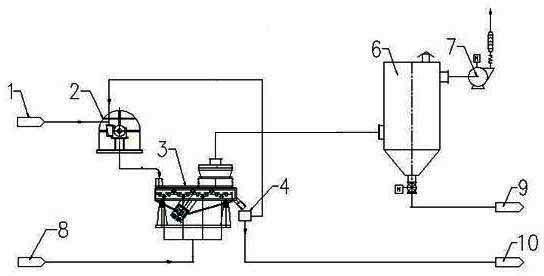
[0023] Add the non-magnetic steel slag powder 1 with a water content of 5% and 20 mm into the vertical roller mill 2. After the vertical roller mill is ground, the fine powder content under the 325 mesh sieve reaches 15%, and the throughput of the mill per hour For 30 tons. After the material is ground, it enters the vibrating powder separator 3. Under the high-frequency and large-amplitude vibration of the vibrating drying powder separator 3, the steel slag powder on the large-grained steel slag falls off from the top, and the high-temperature air 8 sucked by the high-pressure induced draft fan 7 passes through. The air distribution plate 11 of the vibration drying powder separator 3 blows up the steel slag powder, and the steel slag powder is fluidized and dried in the vibration drying powder separator 3 . The classifier 12 on the top of the vibrating drying powder classifier 3 classifies the fine powder, and the qualified steel slag fine powder is collected in the bag filte...
Embodiment 2
[0025] Add the non-magnetic steel slag powder 1 with a water content of 5% and 10 mm into the horizontal roller mill 2. After the horizontal roller mill is ground, the fine powder content under the 325 mesh sieve reaches 20%, and the hourly mill throughput For 70 tons. After the material is ground, it enters the vibration drying powder separator 3. Under the high-frequency and large-amplitude vibration of the vibration drying powder separator 3, the steel slag fine powder on the large-grained steel slag falls off from the top, and the high-temperature air 8 sucked by the high-pressure induced draft fan 7 The steel slag powder is blown up by passing through the wind distribution plate 11 of the vibration drying powder separator 3, and the steel slag powder is fluidized and dried in the vibration drying powder separator 3. The classifier 12 on the top of the vibrating drying powder separator 3 classifies the fine powder, and the qualified steel slag fine powder enters the bag fi...
PUM
| Property | Measurement | Unit |
|---|---|---|
| particle size | aaaaa | aaaaa |
Abstract
Description
Claims
Application Information
 - R&D Engineer
- R&D Manager
- IP Professional
- Industry Leading Data Capabilities
- Powerful AI technology
- Patent DNA Extraction
Browse by: Latest US Patents, China's latest patents, Technical Efficacy Thesaurus, Application Domain, Technology Topic, Popular Technical Reports.
© 2024 PatSnap. All rights reserved.Legal|Privacy policy|Modern Slavery Act Transparency Statement|Sitemap|About US| Contact US: help@patsnap.com