
Manufacturing method of laminated type ceramic electronic element

A technology of electronic components and manufacturing methods, applied in the direction of inductor/transformer/magnet manufacturing, resistance manufacturing, electrical components, etc., can solve the problems of increasing stray capacitance, deteriorating product performance, short-circuiting through holes, etc. The effect of capacitors

Inactive Publication Date: 2011-08-10
SHENZHEN SUNLORD ELECTRONICS
View PDF7 Cites 22 Cited by
  • Summary
  • Abstract
  • Description
  • Claims
  • Application Information

AI Technical Summary

Problems solved by technology

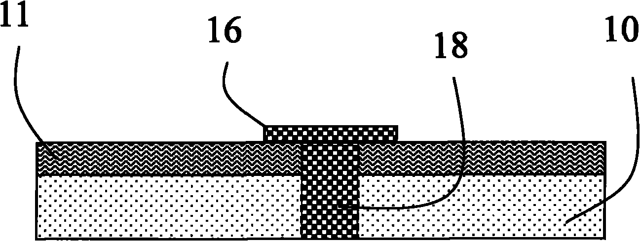
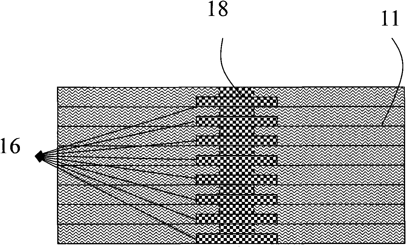
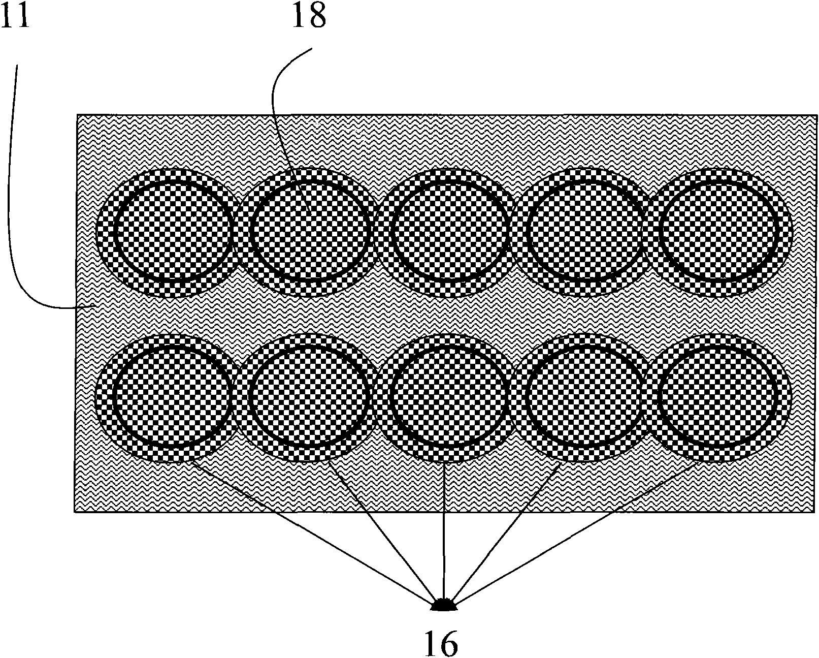
For products with a relatively large size, the above disadvantages are not obvious, but for products with a relatively small size and a large number of electrode layers, the remaining electrodes will form parallel plate capacitors, increasing stray capacitance (such as figure 2 As shown), the performance of the product is deteriorated. In addition, the same layer of ceramic green sheet has many holes and the spacing is small, and the remaining electrodes around the through holes overlap each other, which is easy to cause a short circuit between the through holes (such as image 3 shown)

Method used


Image

  • Manufacturing method of laminated type ceramic electronic element
  • Manufacturing method of laminated type ceramic electronic element
  • Manufacturing method of laminated type ceramic electronic element

Examples


Embodiment Construction

[0037] The present invention will be described below in combination with specific embodiments and with reference to the accompanying drawings.

[0038] a kind of like Figure 4~7 In the manufacturing method of the laminated chip ceramic electronic component shown, the laminated chip ceramic electronic component is a high-frequency magnetic bead with a length of 1.0mm and a width of 0.5mm imitating a bluetooth antenna structure. The overall molding stage has the following steps:

[0039] 1) Tape casting to form ceramic green sheets

[0040] 1.1) Surface coating

[0041] The ceramic slurry is coated on the surface of the PET film carrier sheet 10 to form a ceramic green sheet 11. The components of the coated ceramic slurry and their weight percentages are as follows:

[0042] Ferrite NiCuZn powder 80%;

[0043] Binder: polyvinyl butyral (PVB) resin 15%;

[0044] Dispersant: BYK110 3%;

[0045] Plasticizer: Dibutyl Phthalate (DBP) 2%.

[0046] 1.2) drying coating

[0047] ...


PUM


Abstract

The invention relates to a manufacturing method of a laminated type ceramic electronic element, sequentially comprising the following steps at an integral forming stage: (1) carrying out tape casting to form ceramic raw sheets; (2) arranging through holes; (3) filling slurry into the through holes; (4) printing electrodes; (5) laminating and pressing; and (6) carrying out isostatic pressing processing. The manufacturing method of the laminated type ceramic electronic element is characterized in that the step (3) of filling the slurry into the through holes is to fill conductive slurry into the through holes of the ceramic raw sheets in a screen printing manner and a reverse hole-filing manner; and the reverse hole-filing manner is to fill the conductive slurry into the through holes along a printing scraper downwards to be processed by a silk screen, a load-bearing sheet, the ceramic raw sheets and a printing supporting table plate sequentially. By adopting the reverse hole-filing manner in the manufacturing method, the stray capacitance brought about by the redundant electrodes can be effectively eliminated; and besides, the short circuit among the through holes cannot be caused when the through holes have a large number and small intervals on a same layer of the ceramic raw sheets. The manufacturing method provided by the invention can be widely used for manufacturing the laminated type ceramic electronic element made of ferrite ceramics, alumina glass ceramics, manganese-cobalt-nickel ceramics and zinc oxide ceramics.

Description

technical field [0001] The invention relates to laminated chip ceramic electronic components, in particular to a manufacturing method of laminated chip ceramic electronic components. Background technique [0002] Most of the existing manufacturing methods of laminated ceramic electronic components are to print conductive paste on the surface of the ceramic green sheet to form the electrode structure inside the component, and the electrodes of different ceramic green sheets are connected through the through holes inside the green sheet interconnection; the internal lead-out electrode and the external connection electrode are also connected through the internal through hole of the green sheet. The reliability of multilayer chip ceramic electronic components is basically determined by the reliability of through-hole connections. In the actual manufacturing process, the ceramic green sheet enters the printing process after being opened by a laser; while printing the conductive ...

Claims


Application Information

Patent Timeline
IPC IPC(8): H01C7/02H01C7/04H01C17/00H01C17/065H01F41/00
Inventor 戴春雷刘宁伍检灿郭海
Owner SHENZHEN SUNLORD ELECTRONICS
Learn More