
Micro-beam plasma arc/laser hybrid welding method

A plasma arc and composite welding technology, applied in the field of metal welding, can solve the problems of inability to achieve effective welding of heat-treated aluminum alloys, design of welding methods and processes, heat non-concentration and thermal influence, etc., to achieve small deformation, reduce weld width and The effect of heat-affected zone width and fast welding speed

Inactive Publication Date: 2011-03-30
CRRC QINGDAO SIFANG CO LTD
View PDF1 Cites 19 Cited by
  • Summary
  • Abstract
  • Description
  • Claims
  • Application Information

AI Technical Summary

Problems solved by technology

[0013] In the prior art, the welding method described in the Chinese patent "Method for Continuous Butt Welding Using Plasma and Laser and Method for Manufacturing Metal Pipe Using the Method" with the patent No. 200480043356.8 exists, but the plasma of this method In fact, it includes various flame and arc heating methods. When flame plasma is heated, the heat is not concentrated and the heat-affected zone is very wide. It cannot be well used for materials with good thermal conductivity such as aluminum and copper, let alone heat-treated aluminum alloys. and heat-treated steel and other materials
Arc plasma heating is slightly better than flame plasma heating, but the heat-affected zone is still wider
In addition, the welding method and process described in the 200480043356.8 Chinese patent "Method for Continuous Butt Welding Using Plasma and Laser and Method for Manufacturing Metal Pipe Using This Method" are mainly used for welding metal pipes and some sheet metals, and There is no welding method and process designed specifically for the characteristics of aluminum alloys, especially for the welding of aluminum alloy plates and profiles, a special welding process is required, and this method cannot achieve effective welding of heat-treated aluminum alloys

Method used


Image

  • Micro-beam plasma arc/laser hybrid welding method
  • Micro-beam plasma arc/laser hybrid welding method

Examples


Embodiment Construction

[0030] Below in conjunction with accompanying drawing and specific embodiment the present invention is described in further detail:

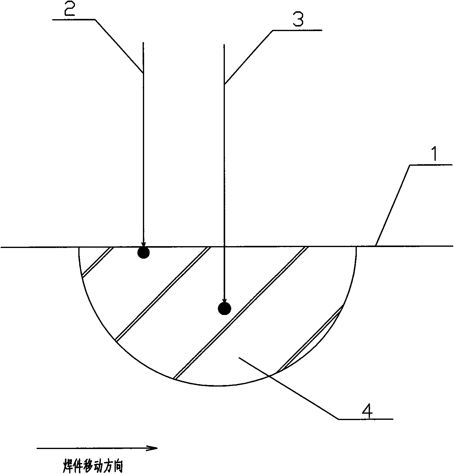
[0031] Such as figure 1 As shown, the hybrid welding method of the present invention uses a micro-beam plasma arc and a laser composite heat source to carry out butt welding of aluminum alloy plates or profiles, wherein an aluminum alloy plate with a thickness of 5 mm, a width of 200 mm, and a length of 1000 mm is taken as an example .

[0032]The micro-beam plasma arc welding torch adopts TK-4 type, the main technical parameters: the working current is 0.3-30A; the arc ignition method is high frequency; the nozzle cooling method is indirect water cooling; the electrode cooling method is indirect water cooling; 0.4MPa; the cooling water inlet temperature is not higher than 45°C; the nozzle aperture range is 0.8-1.5mm, and the electrode diameter is 1.5mm. TK-4 micro-beam plasma arc welding torch can work stably under low current. The cooling sy...


PUM

PropertyMeasurementUnit
Defocus amountaaaaaaaaaa
Angleaaaaaaaaaa

Abstract

The invention relates to a micro-beam plasma arc / laser hybrid welding method, which comprises the following steps: fixing a micro-beam plasma arc transmitter and a laser beam transmitter, providing a workpiece which moves at a constant speed, and forming a mode of micro-beam plasma arc preposition; carrying out initial fusion on the surface of a welded part of the workpiece by micro-beam plasma arcs, then irradiating laser beams to the welded part, thereby deepening the depth of fusion of micro-beam plasma arc welding, and then completing the welding. The welding method of the invention can reduce the reflectance of aluminium alloys to lasers, and improve the absorption rate of aluminium alloys to laser energies, thereby improving the effective heating depth of laser, increasing the depths of fusion of weld joints and effectively reducing the widths of weld joints and heat affected zones; and finally, obtaining weldments which have the advantages of large depth of fusion, extremely small heat affected zone and beautiful appearance.

Description

technical field [0001] The invention relates to a method for butt welding aluminum alloy plates or profiles, specifically a method for butt welding aluminum alloy plates or profiles by simultaneously using two heat sources, micro-beam plasma arc and laser, and belongs to the technical field of metal welding . Background technique [0002] Aluminum alloy has many advantages such as low density, good plasticity, easy processing and forming, no low-temperature brittle transition and atmospheric corrosion resistance. It is widely used in aviation, aerospace, high-speed rail trains or other vehicles. Its physical and chemical properties determine its unique weldability. [0003] At present, for the welding of aluminum alloy materials, especially thick plate aluminum alloys, the fusion and inert gas shielded welding (MIG welding) process is generally used in China. However, the heat input of ordinary fusion welding is relatively large, and the joints are softened, cracked, and po...

Claims


Application Information

Patent Timeline
IPC IPC(8): B23K28/02B23K10/02B23K26/04B23K26/046
Inventor 杨尚磊吕任远罗斌林君山孟立春丁叁叁陈文宾林庆琳
Owner CRRC QINGDAO SIFANG CO LTD
Learn More