
High temperature gradient low melt flow electromagnetic induction heating device

An induction heating device and flowing electromagnetic technology, applied in the field of materials, can solve the problems of unfavorable directional tissue growth, slow heating and cooling rates, and low temperature gradients

Inactive Publication Date: 2010-01-27
NORTHWESTERN POLYTECHNICAL UNIV
View PDF1 Cites 8 Cited by
  • Summary
  • Abstract
  • Description
  • Claims
  • Application Information

AI Technical Summary

Problems solved by technology

[0005] In order to overcome the disadvantages of slow heating and cooling rates in the heating process, low temperature gradient, too much electromagnetic induction heating and stirring force, which is not conducive to the growth of directional tissue in the prior art, the present invention proposes a high temperature gradient and low melt flow Electromagnetic induction heating device

Method used


Image

  • High temperature gradient low melt flow electromagnetic induction heating device
  • High temperature gradient low melt flow electromagnetic induction heating device
  • High temperature gradient low melt flow electromagnetic induction heating device

Examples


Embodiment Construction

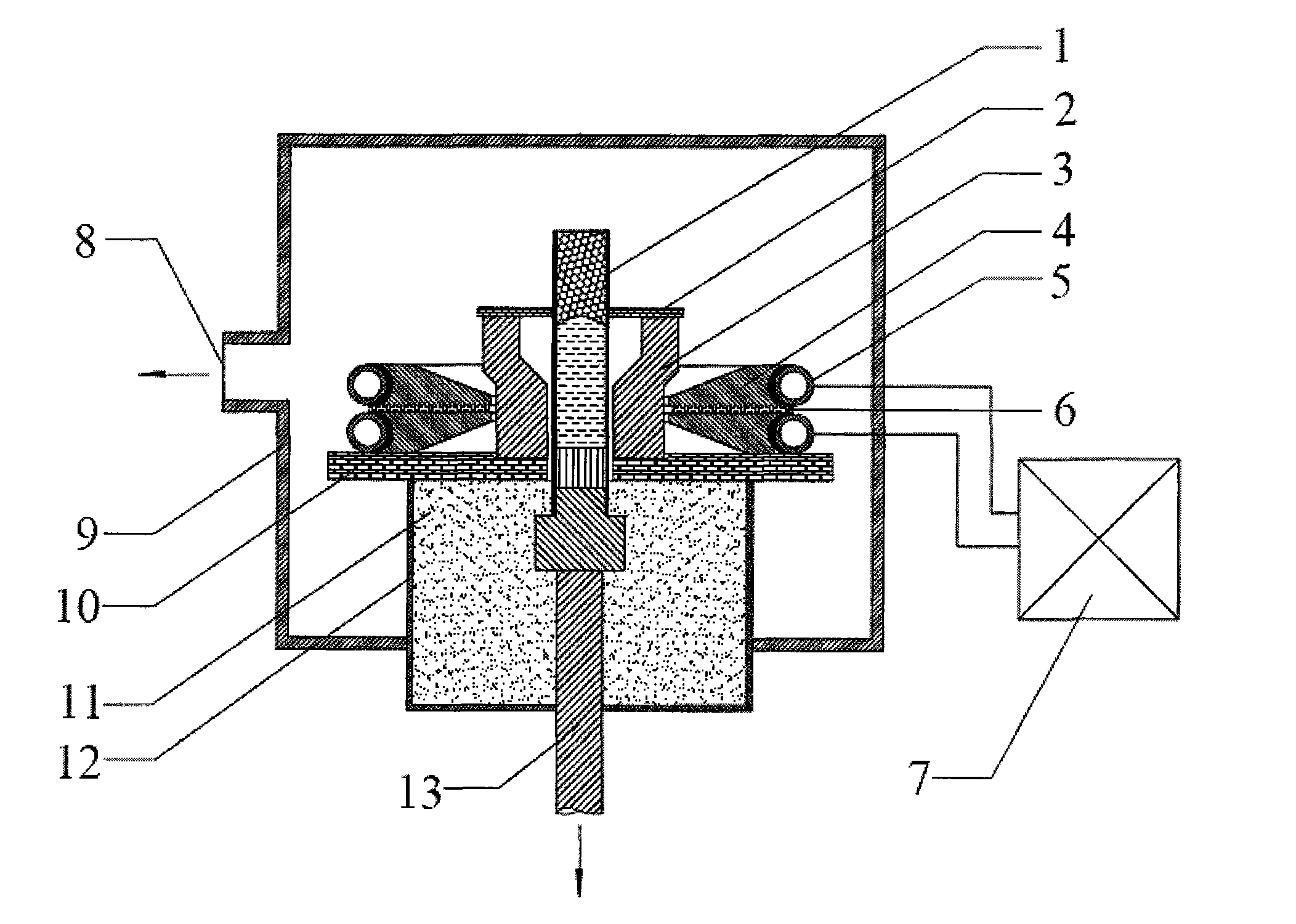
[0023] This embodiment includes a graphite induction heating device, a ceramic crucible 1 , a water-cooled crystallizer 12 , a vacuum chamber 9 , a vacuum extraction system 8 , a pull-down system 13 and a high-frequency induction heating power supply 7 . The frequency of the high-frequency induction heating power supply 7 is 200KHZ, and the outer diameter of the ceramic crucible 1 is 9mm.

[0024] as attached Figure 6 As shown in , the graphite induction heating device is composed of a coil, a high-frequency inductor 4, a graphite heating body 3 and an upper heat insulation board 2. The coil has two turns and is made of a 6mm hollow copper tube, which is set in the groove on the outer surface of the high-frequency inductor, and is seamlessly connected with the high-frequency inductor through the welding structure 14 .

[0025] The ring-shaped high-frequency inductor 4 is made of red copper and has two turns, and its outer peripheral surface has an arc-shaped groove with a di...


PUM


Abstract

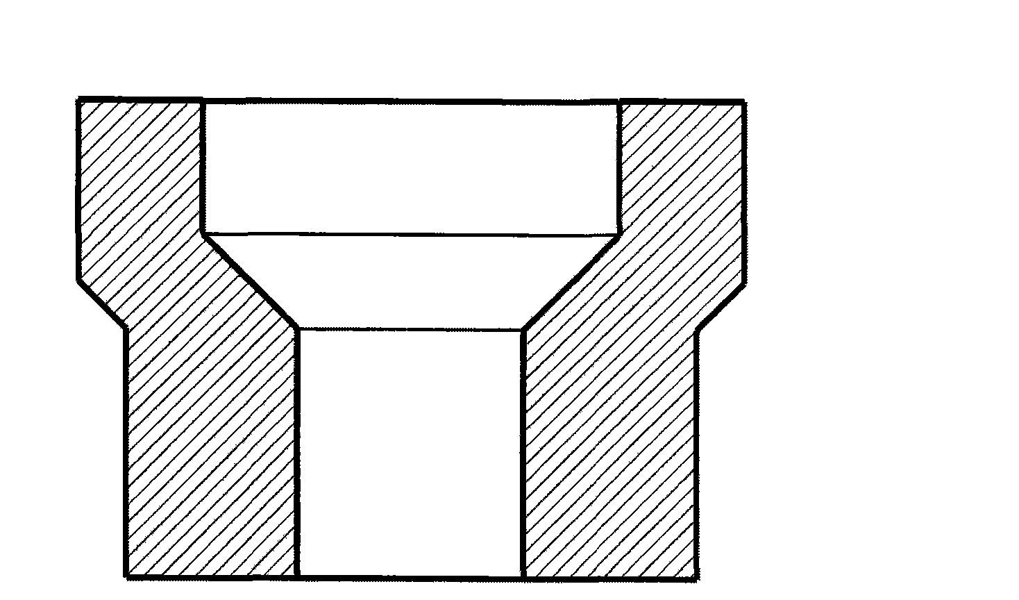
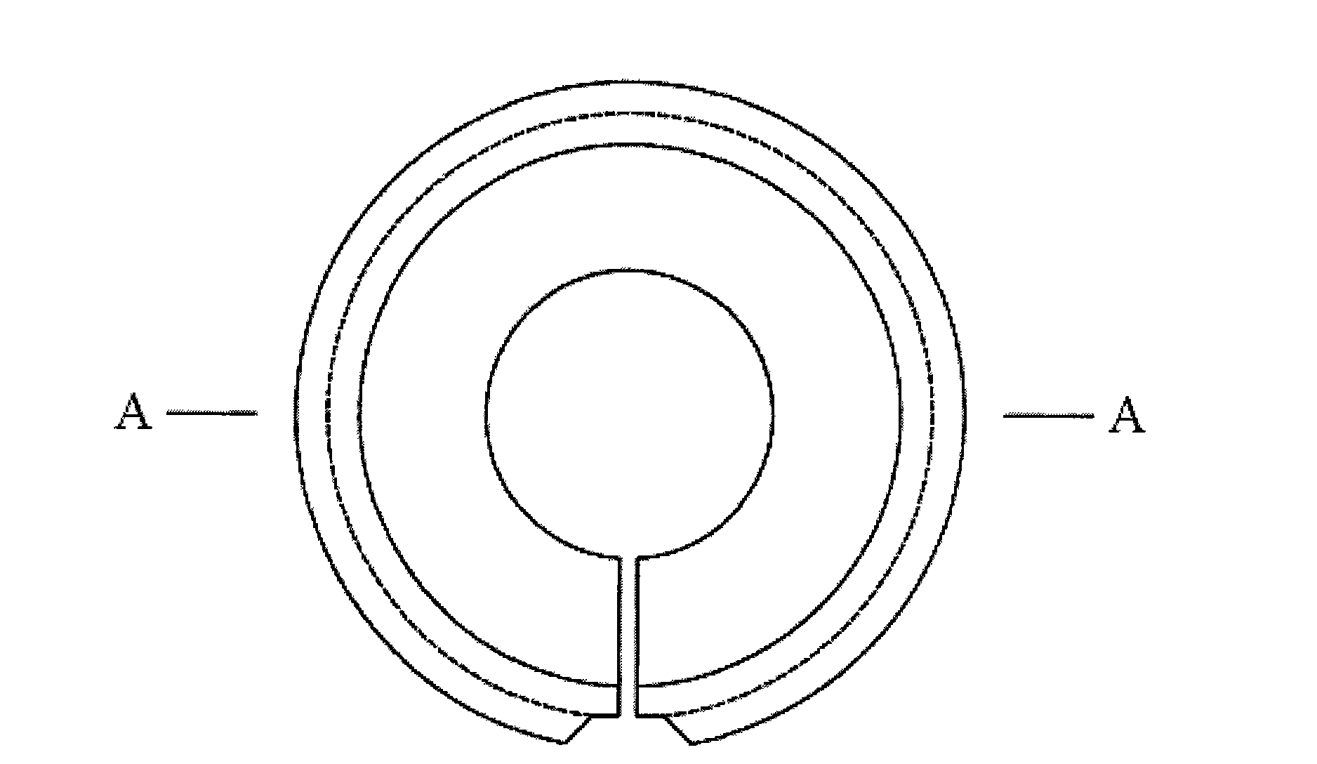
The invention relates to a high temperature gradient low melt flow electromagnetic induction heating device, wherein, a high-frequency inductor (4) has two turns with the upper and lower surfaces being inclined planes to form an inner cone; an insulation board (6) is arranged between the two turns of high-frequency inductors and an open circuit groove is arranged along the direction of the radius. The thickness of the inner circle in the high-frequency inductor is one fourth of that of the outer circle; the inner diameter and the outer diameter of one end of a funnel-type graphite heating body (3) are both greater than the inner diameter and the outer diameter of the other end, and a 45-degree inclined plane is used for the transition between a big end and a small end; the inner diameter of the small end of the heating body (3) is greater than the outer diameter of a ceramic crucible (1); the knife edge part of the high-frequency inductor (4) performs compulsory induction heating on the small end of the graphite heating body (3), and high temperature gradient can be obtained at the leading edge of the melt solid / liquid interface; the big end of the graphite heating body (3) performs preheating on a test bar in the ceramic crucible (1), so as to ensure that the test bar can melt and superheat fully under the high withdrawal rate and the high temperature gradient low melt flow can be realized in the directional solidification process.

Description

1. Technical field [0001] The invention relates to directional solidification control in the field of materials, in particular to an electromagnetic induction heating device with high temperature gradient and low melt flow. 2. Background technology [0002] The directional solidification technology proposed by Bridgman is a major development of modern advanced material processing technology. Compared with castings obtained by ordinary casting methods, the columnar grain structure obtained by directional solidification greatly reduces casting defects such as segregation and porosity, forms grains parallel to the principal stress axis, eliminates transverse grain boundaries and greatly improves the mechanical properties of structural materials. performance. In actual production, the application of directional solidification technology improves the high temperature strength, thermal fatigue performance, creep and durability characteristics of superalloys, and makes a new leap ...

Claims


Application Information

Patent Timeline
Patent Type & Authority Applications(China)
IPC IPC(8): H05B6/26
Inventor 罗文忠沈军傅恒志
Owner NORTHWESTERN POLYTECHNICAL UNIV
Learn More