
Polished sucker rod

A technology for sucking polished rods and nickel-based alloys, applied in drill rods, coatings, metal material coating processes, etc., can solve the problems of difficulty in ensuring the elongation after breaking, reducing the service life of spray welding polished rods, and high production costs. The effect of improving toughness and resistance to crack formation, improving resistance to crack formation and propagation, and improving the ability to resist surface cracks

Active Publication Date: 2009-11-04
黄锦滨 +1
View PDF0 Cites 19 Cited by
  • Summary
  • Abstract
  • Description
  • Claims
  • Application Information

AI Technical Summary

Problems solved by technology

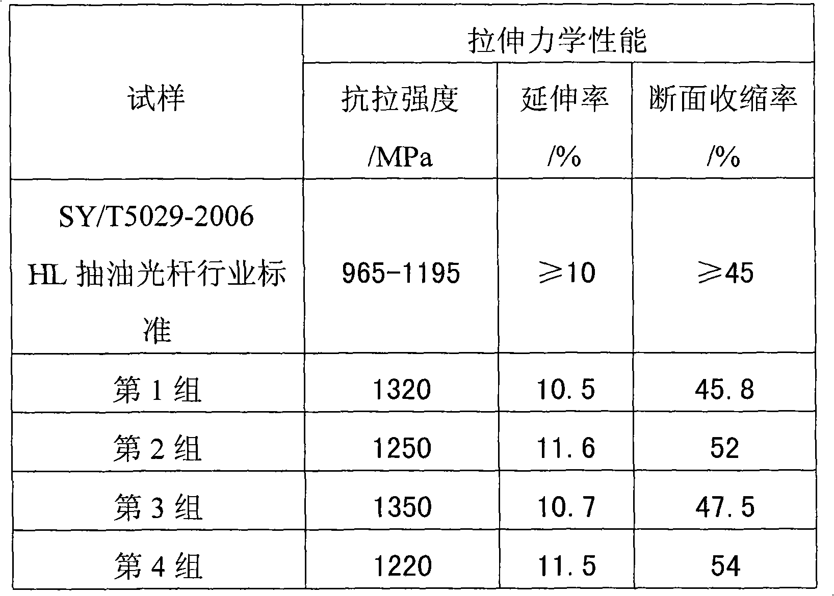
[0005] Among the existing material-type sucker rods / polished sucker rods in oilfields at home and abroad, the 97-type steel in the United States, the FG20 steel and BZ11 steel in China are good representatives, but due to the temperature control of FG20 steel in the production process The requirements are relatively high, and its elongation after breaking (200mm gauge length) is difficult to guarantee to meet the requirements of the SY / T5029-2006 "Sucker Rod" standard on the elongation of H-class oil sucking rods not less than 10%, so domestic oil fields have been for many years There is no polished oil rod made of this material; while American 97-type steel and domestic BZ11 steel oil polished rod fully meet the requirements of the industry standard in terms of performance and show good performance in use, but due to their production costs Too high, far beyond the actual acceptance level of oilfields, making it difficult to promote and apply in domestic oilfields
[0006] At present, there is basically no application of ultra-high-strength oil pumping polished rods with high load-bearing, wear-resistant and corrosion-resistant materials in domestic oil fields. 20CrMo substrates and spray-welded polished rods with nickel-based alloy coatings on the surface are still widely used, which makes them more effective in production, processing and performance. Requirements and other aspects have gradually been difficult to meet the actual needs of oilfields
Especially because the polished rod bears a large bending cyclic load within ten centimeters below the clamp, the fracture at this position becomes the main form of polished rod fracture, and this fracture form is more significant for spray-welded coated polished rods This is mainly due to the unreasonable optimization of the composition of the nickel-based alloy coating and the matching selection of the nickel-based coating and the polished rod base material in the existing spray-welded polished rods in the oil field. Under the action of bending force, the surface of the coating will quickly generate cracks and expand, which seriously reduces the service life of the spray-welded polished rod

Method used


Image

  • Polished sucker rod
  • Polished sucker rod

Examples


Embodiment 1

[0033] A polished oil pumping rod, comprising a base material 1 and a nickel-based alloy coating 2 spray-welded on the surface of the base material 1, the composition of the nickel-based alloy coating in mass percentage is: C: 0.30%, Si: 3.0%, B: 2.0%, Cr: 10.0%, Cu: 12.0%, Fe: 3.0%, and the balance is nickel. The composition of the substrate in terms of mass percentage is: C: 0.13%, Si: 1.30%, Mn: 0.95%, Cr: 1.60%, Nb: 0.04%, Ti: 0.02%, Mo: 0.2%, Ni: 0.2 %, S: 0.010%, P: 0.007%, and the balance is iron. The preparation process of the oil pumping polished rod of the present invention is: cold drawing-upsetting-whole rod normalizing-whole rod tempering-machining-heat treatment such as thermal spraying and remelting of nickel-based alloy coating-coating surface grinding and polishing.

Embodiment 2

[0035] A polished oil pumping rod, comprising a base material 1 and a nickel-based alloy coating 2 spray-welded on the surface of the base material 1, the composition of the nickel-based alloy coating in terms of mass percentage is: C: 0.40%, Si: 2.5%, B: 3.0%, Cr: 8.0%, Cu: 9.0%, Fe: 2.0%, and the balance is nickel. The composition of the substrate in terms of mass percentage is: C: 0.14%, Si: 1.00%, Mn: 1.25%, Cr: 1.40%, Nb: 0.03%, Ti: 0.04%, Mo: 0.1%, Ni: 0.15 %, S: 0.008%, P: 0.010%, and the balance is iron. The preparation process of the oil pumping polished rod of the present invention is: cold drawing-upsetting-whole rod normalizing-whole rod tempering-machining-heat treatment such as thermal spraying and remelting of nickel-based alloy coating-coating surface grinding and polishing.

Embodiment 3

[0037] A polished oil pumping rod, comprising a base material 1 and a nickel-based alloy coating 2 spray-welded on the surface of the base material 1, the composition of the nickel-based alloy coating in terms of mass percentage is: C: 0.10%, Si: 2.2%, B: 2.5%, Cr: 7.5%, Cu: 7.0%, Fe: 5.0%, and the balance is nickel. The composition of the substrate in terms of mass percentage is: C: 0.17%, Si: 0.60%, Mn: 0.80%, Cr: 1.70%, Nb: 0.06%, Ti: 0.03%, Mo: 0.15%, Ni: 0.2 %, S: 0.010%, P: 0.005%, and the balance is iron. The preparation process of the oil pumping polished rod of the present invention is: cold drawing-upsetting-whole rod normalizing-whole rod tempering-machining-heat treatment such as thermal spraying and remelting of nickel-based alloy coating-coating surface grinding and polishing.


PUM


Abstract

A polished sucker rod is characterized by comprising a substrate and a nickel base alloy coating spray welded on surface of the substrate. The nickel base alloy coating is made of the following materials by mass percent: 0%-0.8% of C, 2.0-4.0% of Si, 1.5%-4.5% of B, 5.0%-14.0% of Cr, 5.0%-15.0% of Cu, no greater than 5.0% of Fe and nickel. The MC polished sucker rod has excellent comprehensive mechanical properties, which significantly enhances the tensile strength, and the nickel base alloy coating on the surface has superior wear resistance and corrosion resistance and better bending resistance, which ensures that the polished sucker rod can better satisfy the high load and wear-corrosion service environment of oil fields.

Description

technical field [0001] The invention relates to petroleum equipment, more specifically to an oil pumping polished rod. Background technique [0002] Pumping wells have always been the main method of oil production in oil fields at home and abroad, and polished rods are one of the key components of this type of rod pumping system. As the first sucker rod in the pumping well, the polished oil rod must first bear the gravity of all the sucker rods, pumps and well fluids in the well, as well as various resistance loads generated during the pumping process; because it is in a During the working cycle, it will reciprocate between the downhole well fluid and the atmosphere, and at the same time, it will continue to rub against the rubber oil seal at the wellhead, so it is difficult for ordinary polished rods to withstand such corrosion and wear; in addition, with the current deep oil wells, heavy oil wells With the increasing number of high water-cut wells, it is also necessary to...

Claims


Application Information

Patent Timeline
IPC IPC(8): E21B17/00C22C19/05C23C24/10
Inventor 李艳袁静静
Owner 黄锦滨
Learn More