
Device for recycling waste heat in high temperature steam from rubbish treatment

A high-temperature steam and waste heat recovery technology, applied in the direction of solid waste removal, etc., can solve the problems of excessive energy consumption, multi-energy, air pollution, etc., and achieve the effect of reducing air pollution, saving energy consumption, and reducing heating capacity

Inactive Publication Date: 2009-10-14
SHANDONG MINGLIU KITCHEN WASTE TREATMENT EQUIP CO LTD
View PDF0 Cites 8 Cited by
  • Summary
  • Abstract
  • Description
  • Claims
  • Application Information

AI Technical Summary

Problems solved by technology

Now, there are various garbage disposal machines on the market, which can be roughly divided into two categories. One is to put food waste or feed into the treatment tank and use microbial strains to decompose it. The method is relatively slow. During the decomposition process, the malodorous gas is released into the atmosphere, causing air pollution, seeping out water, and polluting the surrounding soil and groundwater at the same time, causing environmental pollution; the other is to use a garbage processor to dispose of food waste or Feed and other treated materials are heated to promote dehydration or fermentation. The garbage disposer includes a treatment tank. The treatment tank is composed of an inner layer and an outer layer. There is a vacuum layer between the inner layer and the outer layer. There is heating oil in the vacuum layer. There is a stirring device in the treatment tank, a combustion chamber is provided at the lower end of the treatment tank, and fuel oil is installed in the combustion chamber, and the treated matter is stirred by the stirring device, and the fuel oil in the combustion chamber is used to heat up to accelerate the dehydration or fermentation of the treated matter in the treatment tank. During the fermentation process, water vapor evaporated from the processed product will be produced. The water vapor contains foul odor. When the water vapor is discharged into the air, it will cause serious air pollution. In addition, a deodorizing device is installed on the garbage disposal machine to deodorize The device is connected to the treatment tank through the exhaust channel. The deodorization device uses a heating plate to heat the water vapor to 600-800°C for thermal decomposition, and uses a catalyst generator to deodorize the odorous gas. This technology still exists as follows Problem: In order to remove the bad smell, it needs to generate heat energy at 600-800°C, which consumes too much energy
The temperature of water vapor in dehydration or fermentation state is about 100°C, which is relatively low. In order to reach this temperature range, it is necessary to heat the water vapor, resulting in excessive energy consumption.
[0003] Moreover, the deodorizing steam is heated at 600-800°C, which is significantly higher than the temperature in the atmosphere. The high-temperature deodorizing steam will be directly discharged into the air, which will cause thermal pollution
[0004] In order to solve these problems, some use condensers to condense the deodorizing steam and then discharge it. Since there is no hot gas recovery device in the condensation process, the high temperature of the deodorizing steam is discharged into the atmosphere without rational use, and there is a serious waste of energy.
And the heat recovery and reuse in the deodorizing steam cannot be carried out, so there is a problem that the heat in the deodorizing steam cannot be effectively adjusted and utilized

Method used


Image

  • Device for recycling waste heat in high temperature steam from rubbish treatment
  • Device for recycling waste heat in high temperature steam from rubbish treatment
  • Device for recycling waste heat in high temperature steam from rubbish treatment

Examples


Embodiment Construction

[0025] The present invention will be further described below in conjunction with accompanying drawing:

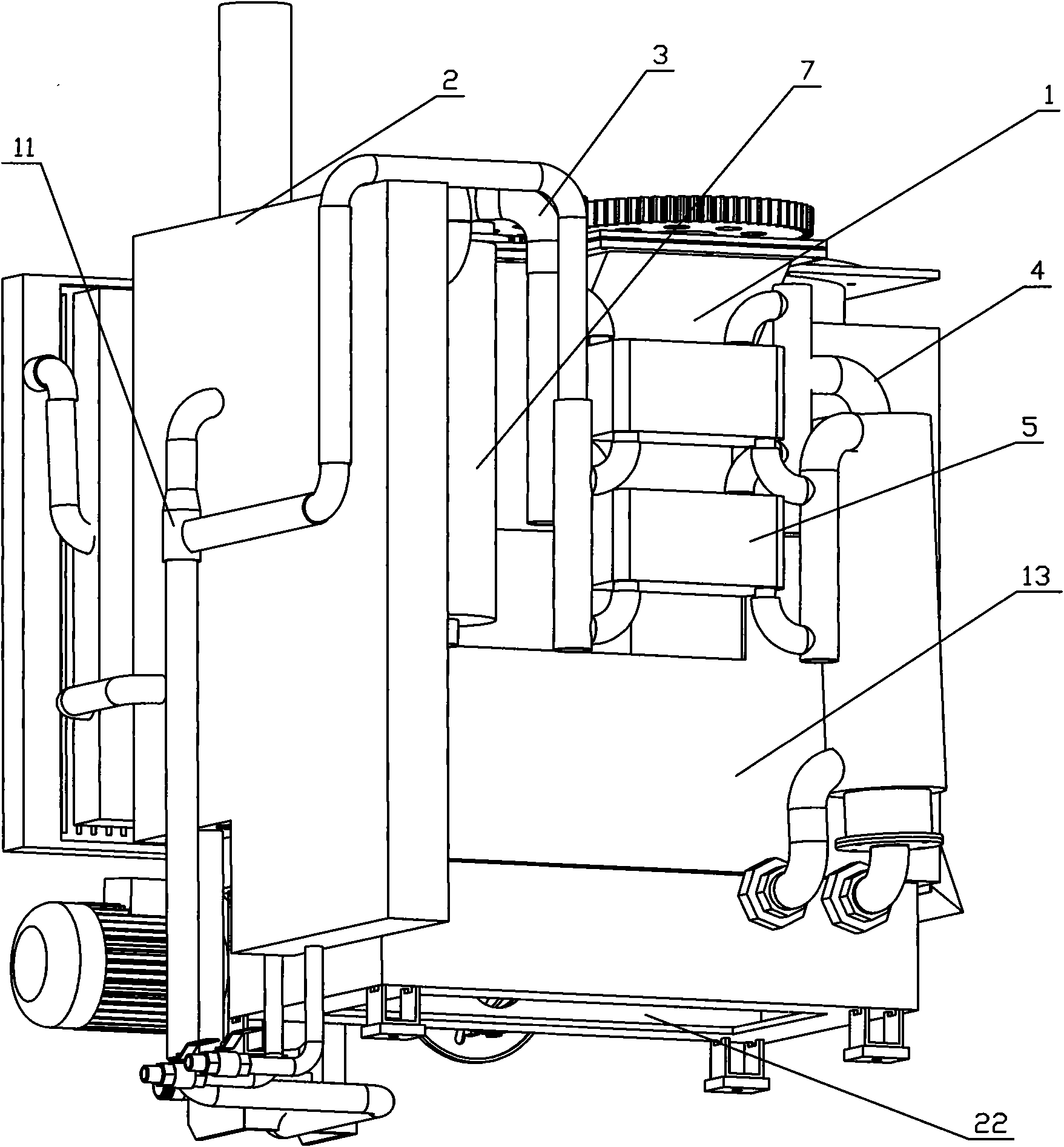
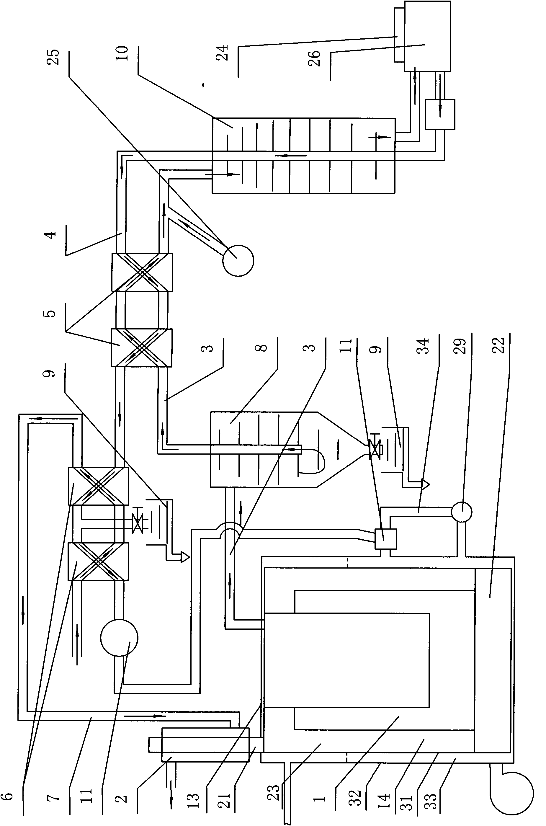
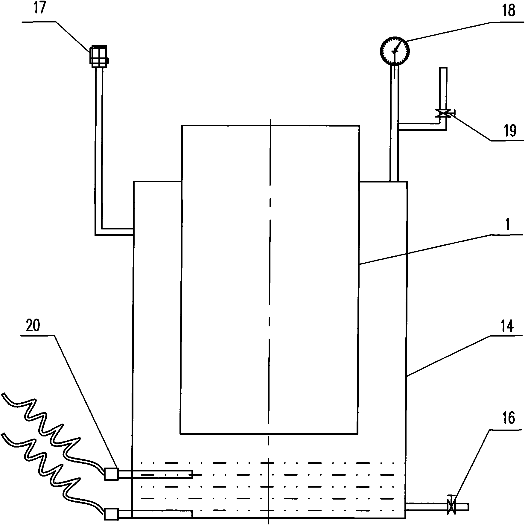
[0026]As shown in the accompanying drawings, a waste heat recovery device for high-temperature steam treated with treated materials includes a treatment tank 1 and a deodorization device. The lower end of the treatment tank 1 is provided with a combustion chamber 22. The heating in the combustion chamber 22 can be heated by a heating plate. Can adopt burner to heat, can also adopt heating plate and burner to heat together, be provided with stirring device in the processing tank 1, the structure of stirring device can be identical with the prior art, this does not go into details, processing tank 1 passes through exhaust channel 3 and The deodorizing device is connected, and it is characterized in that a body of heater 13 is provided, the treatment tank 1 and the combustion chamber 22 are arranged in the body of heater 13, the deodorization device is located in the combustion...


PUM


Abstract

The invention relates to the field of rubbish treating equipment, in particular to a device for recycling waste heat in high temperature steam from rubbish treatment; the device comprises a treating tank, an odor removing device; the treating tank is internally provided with a blending device and communicated with the odor removing device by a gas discharging channel; the device for recycling waste heat is characterized by being provided with a furnace body; the treating tank and a combustion chamber are arranged in the furnace body; the combustion chamber is arranged at the lower end of the treating tank; the odor removing device is arranged in the combustion chamber; the bottom surface of the treating tank is adjacent to the odor removing device; a flue channel is arranged between the treating tank and the furnace body; a gas return channel is arranged between the furnace body and the odor removing device; steam heat exchangers are arranged on the gas return channel and the gas discharging channel; a steam-liquid-heat exchanger is arranged on the gas return channel; and a water cooling channel is arranged on the steam-liquid-heat exchanger. By adopting the structure, the invention has the advantages of reasonable structure, energy conservation, pollution reduction and the like.

Description

technical field [0001] The invention relates to the field of domestic garbage treatment equipment, in particular to a waste heat recovery device for high-temperature steam used for treatment of treated objects. Background technique [0002] With the improvement of people's living standards, domestic garbage has become an urgent problem that people need to solve. The common method used by people is to incinerate garbage, and the harmful gases and various peculiar smells produced by incineration cause air pollution, which is the most troublesome problem for the environmental protection department. Now, there are various garbage disposal machines on the market, which can be roughly divided into two categories. One is to put food waste or feed into the treatment tank and use microbial strains to decompose it. The method is relatively slow. During the decomposition process, the malodorous gas is released into the atmosphere, causing air pollution, seeping out water, and pollutin...

Claims


Application Information

Patent Timeline
Patent Type & Authority Applications(China)
IPC IPC(8): B09B3/00
Inventor 韩弼淳吴人木刘路波周海林
Owner SHANDONG MINGLIU KITCHEN WASTE TREATMENT EQUIP CO LTD
Learn More