Eureka AIR delivers breakthrough ideas for toughest innovation challenges, trusted by R&D personnel around the world.

Electrode wire for wire electric discharging, method for manufacturing the electrode wire, and apparatus for manufacturing bus line thereof

A technology of wire discharge machining and manufacturing method, which is applied in the field of improved wire discharge machining electrode wires, can solve the problems of increased manufacturing costs and complicated procedures, and achieve the effects of reduced production, good discharge performance, and reduced manufacturing costs

Inactive Publication Date: 2009-08-12
OKI ELECTRICAL CABLE
View PDF4 Cites 8 Cited by
  • Summary
  • Abstract
  • Description
  • Claims
  • Application Information

AI Technical Summary

Problems solved by technology

[0021] However, this method requires a complicated process of coating and drying a slurry mainly composed of zinc powder, and then coating, drying and heat-treating a slurry mainly composed of zinc powder having a zinc concentration lower than the above, Then, cold drawn
This method increases the manufacturing cost

Method used


Image

  • Electrode wire for wire electric discharging, method for manufacturing the electrode wire, and apparatus for manufacturing bus line thereof
  • Electrode wire for wire electric discharging, method for manufacturing the electrode wire, and apparatus for manufacturing bus line thereof
  • Electrode wire for wire electric discharging, method for manufacturing the electrode wire, and apparatus for manufacturing bus line thereof

Examples


no. 1 Embodiment

[0064] The first embodiment (Example No1 to No4)

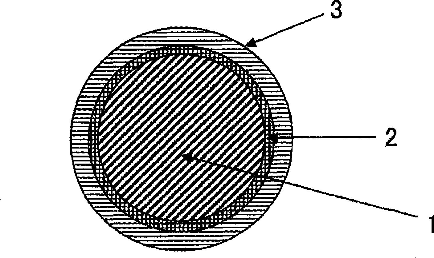
[0065] 65 / 35 brass wire (copper 65% by weight / zinc 35% by weight) with a wire diameter of 1.2 mm through melting, casting, and wire drawing processes is used as the core wire 6, and the image 3 The pickling, water washing, and flux tank 4 that constitute a part of the hot-dip coating apparatus are shown to wash the surface, pass it through the coating tank 5 that maintains pure zinc at 460°C, and then pass it through the coating tank 5 Pull vertically and perform blowing treatment, thereby forming a copper-zinc alloy layer by mutual thermal diffusion at the interface where the brass wire and zinc are in contact, and for the purpose of studying, make the upper layer of the copper-zinc alloy layer The range of the immersion time of the pure zinc layer was changed to four examples of 0.5 second, 0.7 second, 1.0 second, and 1.2 seconds to manufacture the plated bus bar 7 of the electrode wire.

[0066] For blowing treatment, in ...

no. 2 Embodiment

[0069] The 2nd embodiment (embodiment No5 and No6)

[0070] Electrode wires with a diameter of 0.25 mmφ were produced under the same conditions as in the first embodiment above, except that the temperature of the hot-dip coating tank was 440° C. and the immersion time was 0.5 second and 1 second.

no. 3 Embodiment

[0071] The 3rd embodiment (embodiment No7 and No8)

[0072] Electrode wires with a diameter of 0.25 mmφ were produced under the same conditions as in the first embodiment above, except that the temperature of the hot-dip coating tank was set to 500° C. and the immersion time was set to 0.5 second and 1 second.


PUM

PropertyMeasurementUnit
thicknessaaaaaaaaaa
thicknessaaaaaaaaaa
thicknessaaaaaaaaaa

Abstract

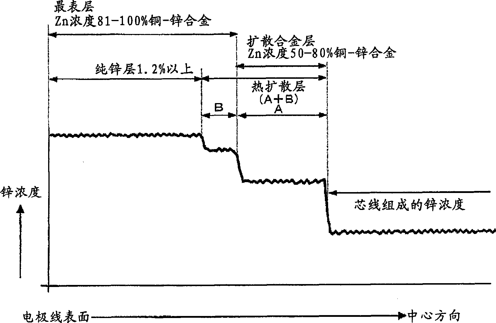
An electrode wire for wire electrodischarge machining includes a core made of copper or copper alloy, a pure zinc layer formed by hot-dip galvanizing the core, and a relatively thin copper-zinc alloy layer formed by mutual thermal diffusion across the interface between the pure zinc layer and the core and having a zinc concentration gradient. The electrode wire is not cracked during its production. The thickness of the copper-zinc alloy layer, the gradient of zinc concentration, and the thickness of the outermost pure zinc layer can be controlled by selecting the dipping time and the temperature of the hot-dip galvanizing bath as appropriate. By blowing a non-oxidizing gas from a bath surface zinc purifying and wiping device disposed above the bath surface through which the core emerges from the hot-dip galvanizing bath, the pure zinc bath surface is kept exposed and runs and uneven thickness of the galvanizing layer are prevented.

Description

technical field [0001] The present invention relates to an improved electrode wire for wire electrical discharge machining, its manufacturing method and its bus bar manufacturing device. Background technique [0002] The so-called wire electrical discharge machining refers to generating a discharge phenomenon between the electrode wire for electrical discharge machining and the workpiece, and cutting the workpiece by the heat energy caused by the discharge, so it is especially suitable for complex shapes such as metal molds. metal processing. [0003] In terms of such electrical discharge machining, there are the following requirements: a. The processing speed is fast; b. The amount of metal powder generated when the electrode wire is continuously moved is small; c. The surface finish and dimensional accuracy of the workpiece are good; d. The positioning performance of measuring the relative position of the electrode wire and the workpiece is good. [0004] As the electrod...

Claims


Application Information

Patent Timeline
Patent Type & Authority Applications(China)
IPC IPC(8): B23H7/08C23C2/06
CPCC23C2/28B23H7/08C23C2/06C23C2/261C23C2/29
Inventor 佐藤弘史伊豆井功夫鹫尾伸幸藤冈信隆吉本雅一
Owner OKI ELECTRICAL CABLE
Why Eureka
Eureka Blog
Learn More