
Process for producing clad material and equipment therefor

A technology of composite materials and manufacturing methods, which is applied in the direction of manufacturing tools, welding equipment, welding equipment, etc., and can solve problems such as abnormal joint foaming quality, low quality, poor adhesion of core material and side material, etc.

Active Publication Date: 2008-10-29
KOBE STEEL LTD
View PDF1 Cites 3 Cited by
  • Summary
  • Abstract
  • Description
  • Claims
  • Application Information

AI Technical Summary

Problems solved by technology

Therefore, since the ingot for the core material and the hot-rolled material for the side material have different surface conditions, when the two are laminated together for composite hot rolling, there is a problem that poor adhesion between the core material and the side material is likely to occur.
Moreover, in order to improve the adhesion between the core material and the side material, in the composite hot rolling, it must be multi-pass rolling under light pressure, and the productivity of the composite hot rolling is reduced.
[0008] (3) When hot-rolled materials are used as side members, the control of the surface state and flatness (especially the flatness in the longitudinal direction) of the rolled plate is only carried out by rolls. In addition, due to hot rolling on the surface of the rolled plate Since an oxide film is formed, it is difficult to control the surface state and smoothness, and it is impossible to prevent poor adhesion between the core material and the side material
[0009] (4) When poor adhesion between the core material and the side material occurs, the productivity of the composite material will be lowered, and the specified composite rate will not be obtained, and the quality will be lowered due to quality abnormalities such as joint blisters. , the problem of lower corrosion resistance due to poor adhesion also occurs

Method used


Image

  • Process for producing clad material and equipment therefor
  • Process for producing clad material and equipment therefor
  • Process for producing clad material and equipment therefor

Examples


Embodiment Construction

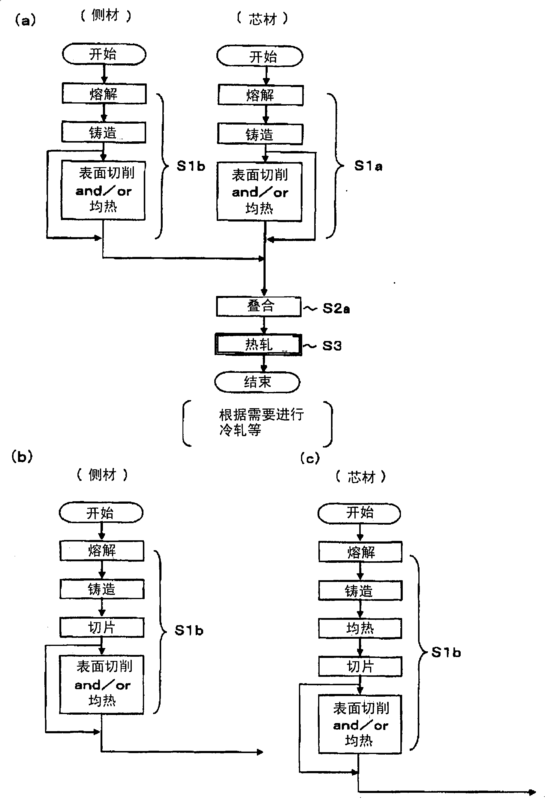
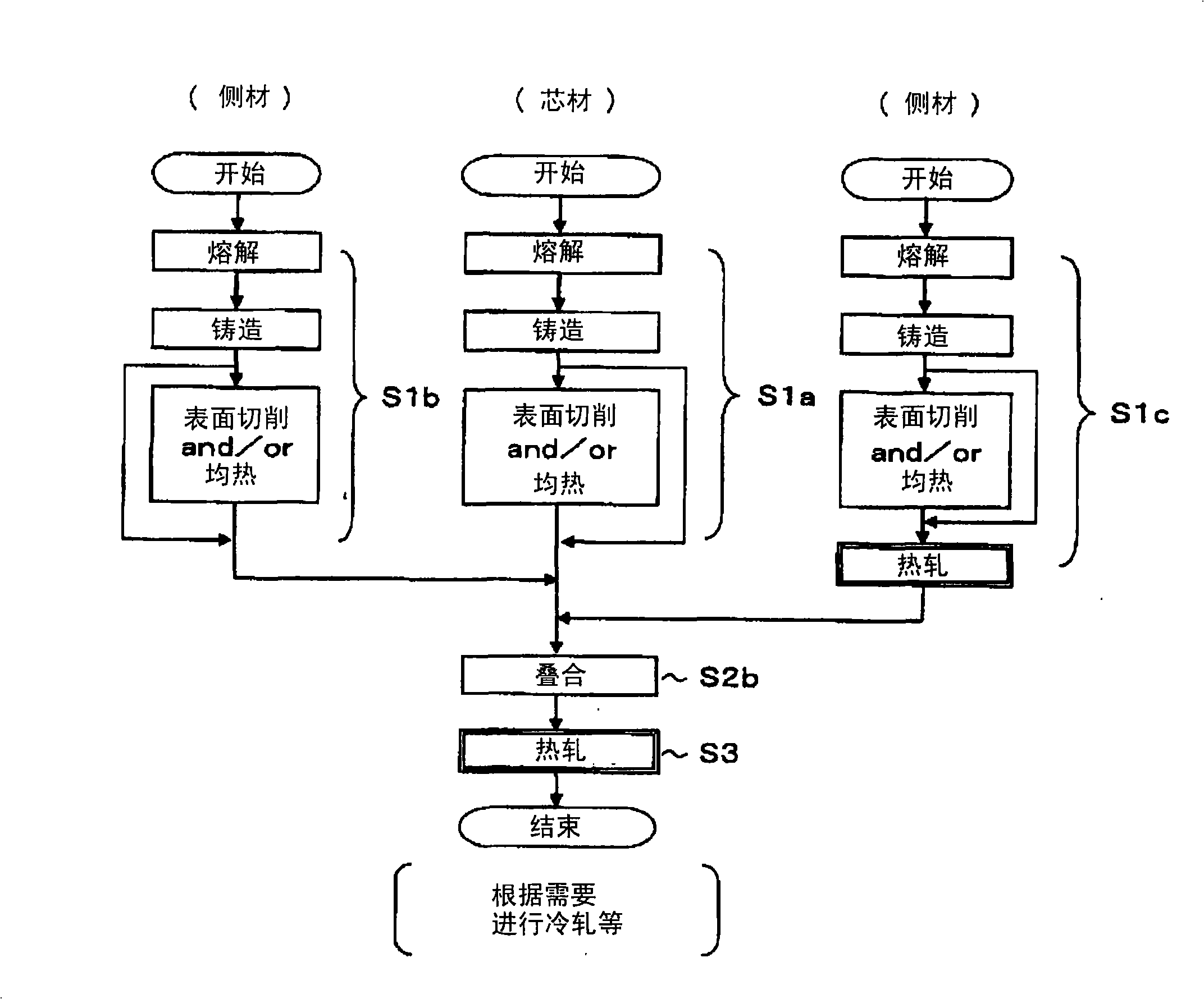
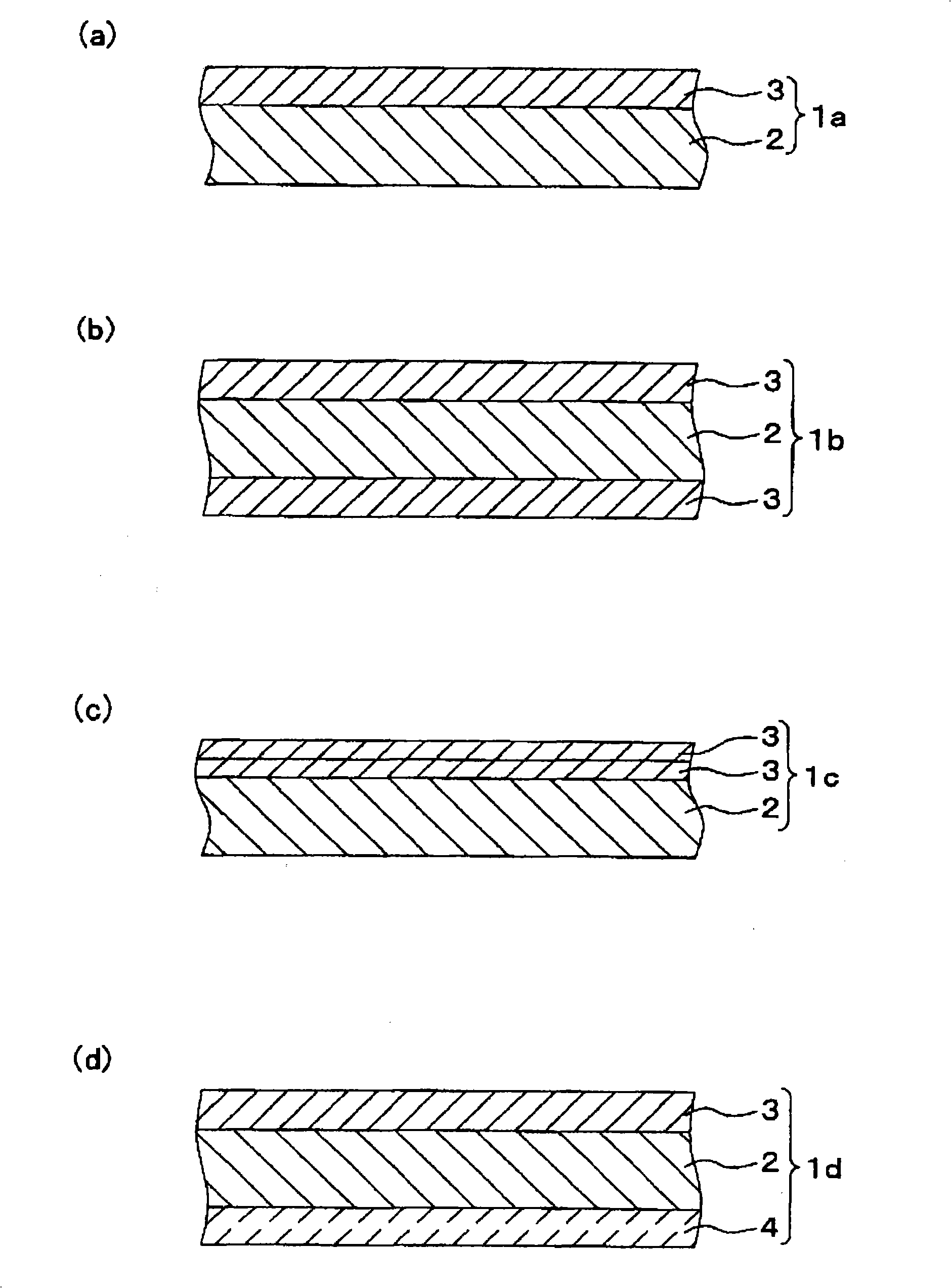
[0088] Next, the method for producing the composite material of the present invention will be described in detail with reference to the drawings. In addition, in the drawings referred to, Fig. 1 (a), Fig. 1 (b), Fig. 1 (c), Fig. 2 are figures showing the flow of the manufacturing method of the composite material, and Fig. 3 is a diagram showing the composition of the composite material Cross-sectional view, Fig. 4~Fig. 7 is the schematic diagram showing the outline of core material preparation process or side material preparation process, Fig. 8 (a) is the schematic diagram showing the composition of laminated parts, Fig. 8 (b) is the thermal diagram showing composite material A schematic diagram of a rolling process.

[0089]The manufacturing method of the composite material of the present invention is applicable to any composite material consisting of a core material and one or more side materials laminated on one or both sides of the core material, and they can be produced....


PUM

PropertyMeasurementUnit
surface smoothnessaaaaaaaaaa
thicknessaaaaaaaaaa
thicknessaaaaaaaaaa

Abstract

A process for producing a clad material, which excels in productivity, facilitating control of the surface condition and flatness of side material member, and which suppresses bonding failure; and equipment therefor. There is provided a process for producing a clad material composed of a core material and, superimposed on one surface or both surfaces thereof, one or two or more side materials, comprising the clad material preparation step of preparing a core material ingot through melting and casting of a metal for core material in the core material preparation step and preparing a side material ingot through melting and casting of a metal for side material with a component formulation different from that of the metal for core material in the side material preparation step; the laminating step of laminating one surface or both surfaces of the core material ingot at given position with the side material ingot as a side material to thereby obtain a laminate; and the cladding hot rolling step of carrying out hot rolling of the laminate to thereby obtain a clad material.

Description

technical field [0001] The present invention relates to a manufacturing method and manufacturing equipment of composite materials used for heat exchangers of automobiles and the like. Background technique [0002] Generally, composite materials used for heat exchangers such as intercoolers, oil coolers, radiators, condensers, evaporators, and heaters for automobiles are used by rolling side materials. [0003] For example, Patent Document 1 describes a conventional general method for producing a composite material for heat exchangers as follows. First, the aluminum alloy for the core material and the aluminum alloy for the side material (sacrificial anode material and brazing material in Patent Document 1) are melted and cast by continuous casting, and homogenized heat treatment is performed as necessary. Next, the aluminum alloy ingots for side materials are respectively hot rolled (refer to S11a and S11b in FIG. 14 , homogenization heat treatment is referred to as soaking...

Claims


Application Information

Patent Timeline
Patent Type & Authority Applications(China)
IPC IPC(8): B23K20/04B23K35/22B23K35/40C22F1/04B23K103/10
Inventor 高田昌行西冈靖展西村友宏德田健二植田利树森下诚稻叶隆鹤野招弘加藤良则腰越史浩谷川正树坂下直己原田健治四方实人池田昌则
Owner KOBE STEEL LTD
Learn More