
Capacitor type microphone chip

A condenser microphone and chip technology, applied in the field of microphones, can solve the problems of adhesion between the diaphragm and the back pole, increase the strength of the back pole, increase the process steps, etc., so as to reduce the adhesion between the diaphragm and the back pole, improve the yield, cantilever Soft structure effect

Active Publication Date: 2008-09-24
WEIFANG GOERTEK MICROELECTRONICS CO LTD
View PDF10 Cites 23 Cited by
  • Summary
  • Abstract
  • Description
  • Claims
  • Application Information

AI Technical Summary

Problems solved by technology

At present, the reported methods include: the patent US6012335 uses a thick gold layer as the back electrode; the patent US6677176B2 uses a composite metal film as the back electrode, which reduces the stress and increases the thickness; the US6140689 patent uses a single crystal silicon layer in the SOI silicon wafer as the back electrode ; US6667189B1 adopts electrochemical corrosion to make a low-stress thick monocrystalline silicon back electrode; US6532460B2 makes a special structure to increase the strength of the back electrode, most of which are complicated in process and high in production cost
[0006] After obtaining a soft diaphragm and a rigid back electrode, the problem of adhesion between the diaphragm and the back electrode must also be solved. So far, there are many methods. The more effective method is to make anti-adhesion protrusions, but it needs to increase the process steps and increase the cost.

Method used


Image

  • Capacitor type microphone chip
  • Capacitor type microphone chip
  • Capacitor type microphone chip

Examples


Embodiment 1

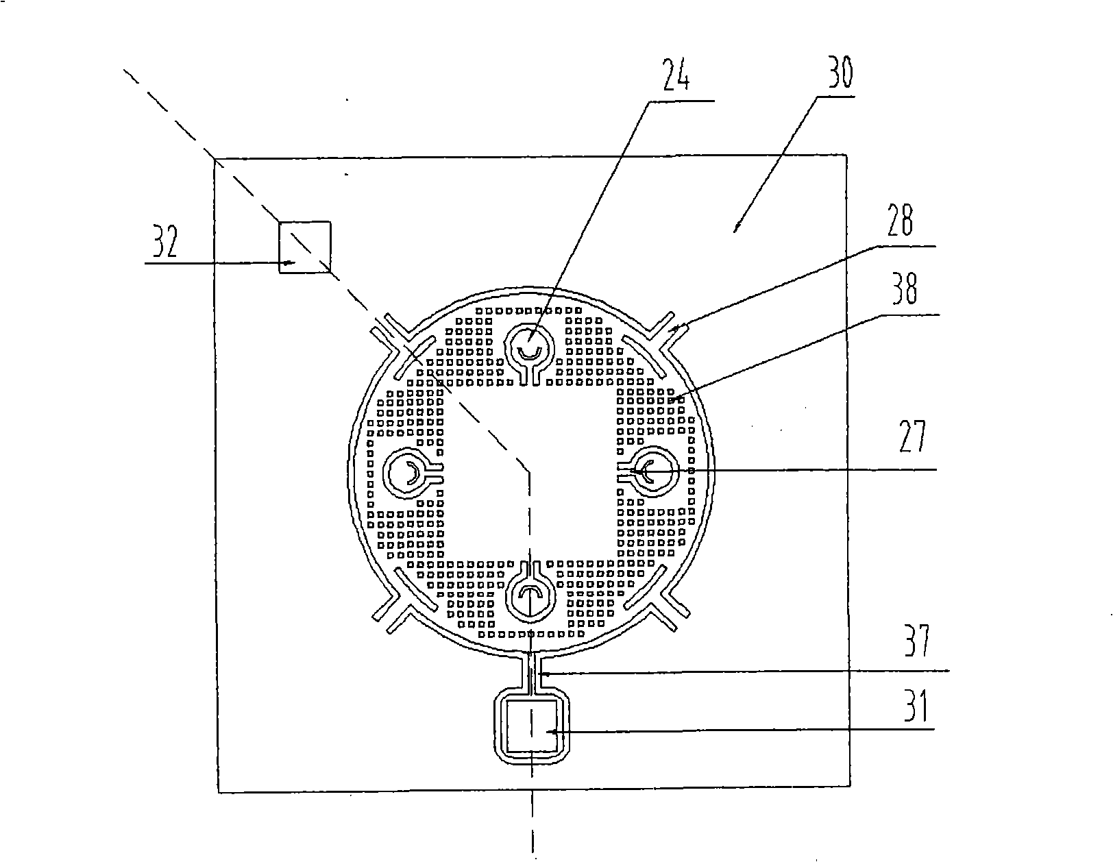
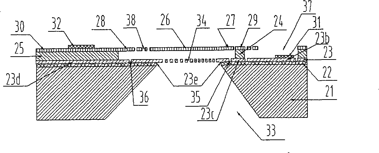
[0061] Such as Figure 1-14 Shown is the first embodiment of the present invention, which is the planar composite cantilever capacitive microphone chip structure of the present invention, as figure 1 , figure 2 As shown, its feature is that the diaphragm is supported by a planar composite suspension beam structure composed of inner suspension beams and outer suspension beams, and only the central part of the back pole is suspended in the air. From bottom to top: base 21, insulating layer 22, conductive layer 23, and inner suspension beam support 24 , an outer cantilever beam support 25, a diaphragm 26, an inner cantilever beam 27, an outer cantilever beam 28, an inner cantilever beam frame 29, an outer cantilever beam frame 30, and a lower electrode 31 and an upper electrode 32.

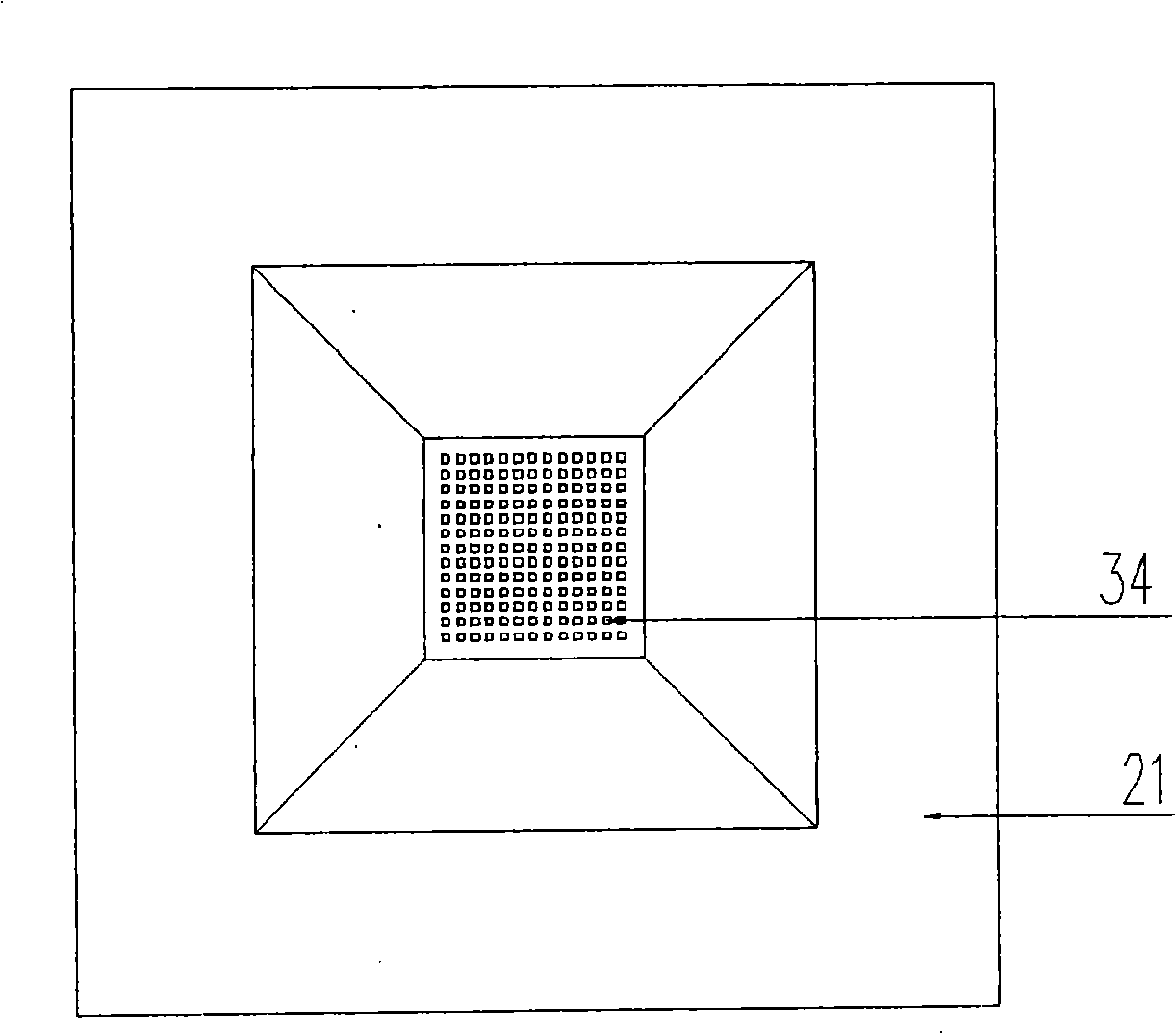
[0062] Wherein, there is a through hole in the center of the base 21 and the insulating layer 22 , which is the back cavity 33 . The substrate 21 is a semiconductor material, which can be silicon,...

Embodiment 2

[0071] Such as Figure 15-22 Shown is the first embodiment of the present invention, which is the chip structure of the three-dimensional composite suspension beam capacitive microphone of the present invention, as Figure 15 , Figure 16 As shown in the figure, it is characterized in that the diaphragm is supported by a three-dimensional suspension beam structure through the upper suspension beam and the lower suspension beam; only the central part of the back pole is suspended. From bottom to top: base 21, insulating layer 22, conductive layer 23, lower cantilever beam support 24, upper cantilever beam support 25, diaphragm 26, upper cantilever beam 28, upper cantilever beam frame 30, and lower electrode 31, upper electrode 32 .

[0072] Wherein, there is a through hole in the center of the base 21 and the insulating layer 22 , which is the back cavity 33 . The substrate 21 is a semiconductor material, which can be silicon, and the back cavity 33 at the center of the silico...


PUM


Abstract

The invention discloses a capacitive microphones chip, which relates to a microphone technology. The capacitive structure is that a vibration film is at the upper part and a back electrode is at the lower part. The vibration film is supported by a plane compound suspension girder or a vertical suspension girder so that the stress is distributed uniformly when the vibration film vibrates. The connection between the vibration film and the back electrode can be effectively reduced and the yield rate also can be improved; the suspension girder structure is soft and the vibration film has a good vibration characteristic. Only the center part of the back electrode is suspended and the surrounding part thereof is covered on a substrate. The supporting of the substrate increases the rigidity of the back electrode; a stiffener can be arranged on the suspension part of the back electrode; therefore, the rigidity of the back electrode can be further improved. The edge of the vibration film is provided with numerous small holes which can release an initial sacrificial layer between the vibration film and the back electrode coordinating with acoustic holes on the suspension part in the back electrode, as well as have an improvement effect to the acoustic characteristics of the microphones. The capacitive microphones chip has the characteristics of high sensitivity, low noise, and wide frequency band. The chip has a small volume. The manufacturing process is simple and batch production is easy to be carried out.

Description

technical field [0001] The invention relates to the technical field of microphones, in particular to semiconductor capacitive microphone chips. Background technique [0002] The research on semiconductor microphone chips has a history of more than 20 years, during which various types of microphones have been developed and implemented on silicon chips. Among them, the most important and popular one is the condenser silicon microphone. Capacitive silicon microphones not only have the characteristics of small size, high sensitivity, good frequency response characteristics, and low noise, but more importantly, they have a wide operating temperature and are suitable for SMT and other automated production lines and harsh working environments. [0003] The condenser microphone chip is an acoustic sensor manufactured by micromachining technology, and its functional structure is a flat plate capacitor composed of a diaphragm and a back electrode. The diaphragm vibrates under the ac...

Claims


Application Information

Patent Timeline
IPC IPC(8): H04R19/01H04R19/04B81B7/02
Inventor 宋青林陶永春庞胜利
Owner WEIFANG GOERTEK MICROELECTRONICS CO LTD
Learn More