Eureka AIR delivers breakthrough ideas for toughest innovation challenges, trusted by R&D personnel around the world.

Vacuum tube direct-insertion type solar hot water system

A solar hot water and vacuum tube technology, applied in the field of solar energy utilization systems, can solve the problems of uncontrollable water temperature, easy to explode tubes, low water outlet pressure, etc., achieve the best heat exchange effect and use effect, improve antifreeze performance, ensure water effect of temperature

Inactive Publication Date: 2008-03-26
BEIJING SIJI MICOE SOLAR ENERGY TECH
View PDF0 Cites 5 Cited by
  • Summary
  • Abstract
  • Description
  • Claims
  • Application Information

AI Technical Summary

Problems solved by technology

The vacuum tube in-line non-pressurized solar water heater dominates the solar water heater market due to its economical benefits and simple installation, but it has the following disadvantages: the water outlet pressure is low, and it is inconvenient for users on the top floor; Explosion of tubes; due to scale formation in the vacuum tube, the efficiency will gradually decrease; after long-term use of the water tank, a large amount of scale will be deposited, which will affect the water quality and be unfavorable to health; in cold regions, the tubes will easily explode in winter, and the antifreeze performance is poor
The water temperature in the water tank is uncontrollable, and scald accidents are prone to occur in summer
Heat pipe pressurized solar water heater solves the problems of low water outlet pressure and vacuum tube explosion, but because the heat conduction element used in the pressurized water heater is a heat pipe, the performance of the heat pipe is prone to attenuation due to the process and material; and the heat pipe heat conduction head Local high temperature, more serious scale deposition, and more obvious thermal efficiency attenuation
In addition, the processing technology is complicated and the cost is high, which seriously restricts its development

Method used


Image

  • Vacuum tube direct-insertion type solar hot water system

Examples


Embodiment Construction

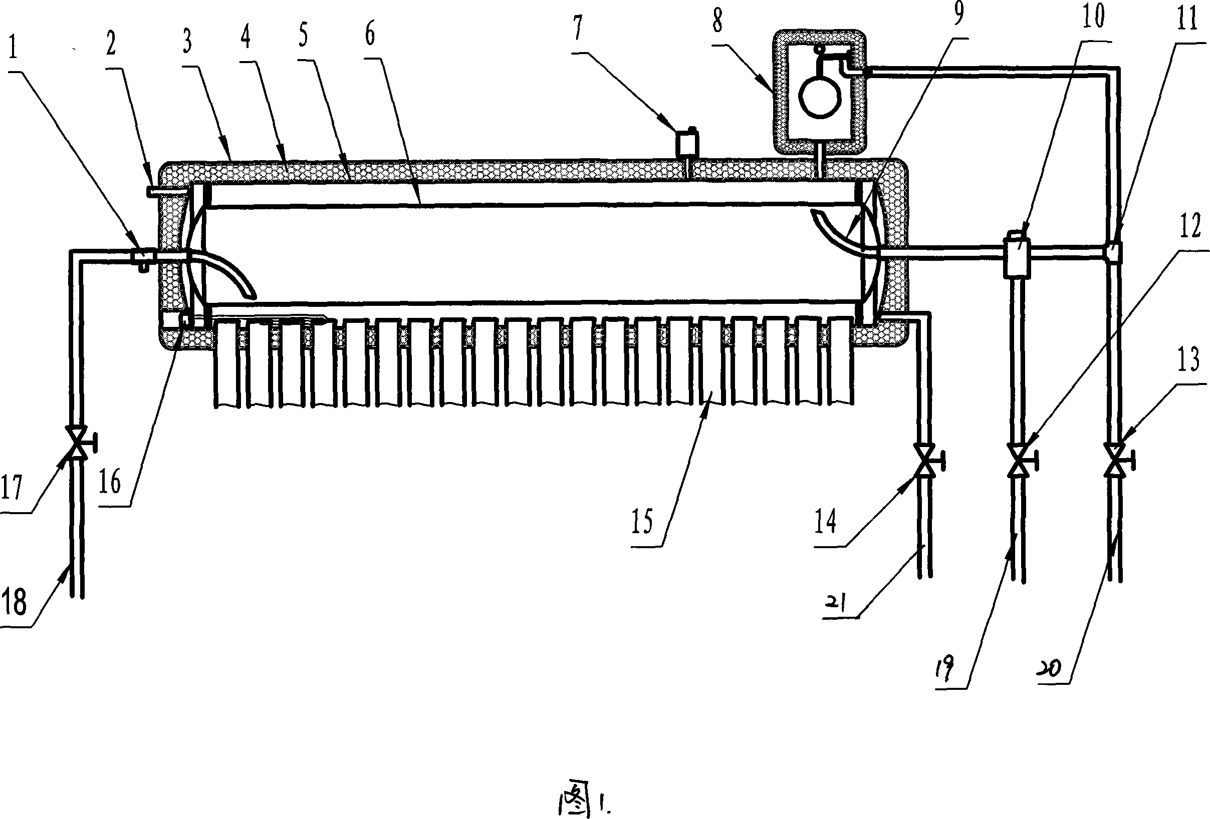
[0011] As shown in the figure: 1. Safety valve, 2. Reserved interface, 3. Water tank shell, 4. Insulation layer, 5. Hot water storage tank, 6. Pressure liner, 7. Air valve, 8. Automatic Compensation device, 9. Hot water outlet pipe, 10. Thermostatic valve, 11. Tap water tee, 12. Water valve, 13. Tap water ball valve (normally open), 14. Ball valve (normally closed, spare), 15. Vacuum tube, 16 . Electric heater, 17. Maintenance ball valve (normally open), 18. Cold water pipe, 19. Water pipe, 20. Tap water pipe, 21. Spare hot water pipe.

[0012] The vacuum tube in-line pressurized solar water heating system includes a hot water storage tank 5 and a heat-absorbing vacuum tube 15 . The hot water storage tank 5 is provided with an air valve 7 and a reserved interface 2 . The hot water storage tank 5 is provided with an electric auxiliary heating device 16 and a heat-exchanging pressure-bearing liner 6 , and the heat-exchanging pressure-bearing liner 6 is arranged concentrically wi...


PUM


Abstract

This invention is a vacuum pipe in-line bearing solar energy hot water system. It includes heat storage water tank and heat absorbing vacuum pipe. Concentrically arranged heat transfer bearing inner bags are assembled inside of the heat storage water tank. The water containing capacity of the heat transfer bearing inner bag is 3.5-4.5 / 1 times to that of the heat storage water tank. One end of the heat transfer bearing inner bag connects to cold water inlet pipe. The cold water inlet pipe is arranged with safety valve and normally open valve. The other end of heat transfer bearing inner bag connects to hot water outlet pipe. The hot water outlet pipe and tap water pipe are paralleled connected into constant temperature valve. The water outlet opening of constant temperature valve connects to the water using pipe. The top of heat storage water tank is arranged with automatic water compensating device. The added heat transfer bearing inner bag can solve the bearing question. The automatic water compensating tank solves the water loading question. The constant temperature valve solves the high temperature water output question. The water in heat storage water tank is just used as heat storage medium. Thus, the heat storage water tank jacket is always filled with hot water. It greatly increases the anti-freeze capacity of water heater in cold area.

Description

technical field [0001] The invention relates to a solar energy utilization system, in particular to a vacuum tube in-line pressurized solar water heating system. Background technique [0002] Solar water heaters are widely used due to their energy-saving and environmental protection features, and the Chinese government also vigorously supports the application of solar water heaters in buildings. However, some shortcomings of the solar water heater itself have limited the momentum of its market development. Solar water heaters currently on the market are roughly divided into two types: one: vacuum tube in-line non-pressurized water heaters; two: heat pipe pressurized solar water heaters. The vacuum tube in-line non-pressurized solar water heater dominates the solar water heater market due to its economical benefits and simple installation, but it has the following disadvantages: the water outlet pressure is low, and it is inconvenient for users on the top floor; Explosion o...

Claims


Application Information

Patent Timeline
IPC IPC(8): F24J2/00F24J2/05F24J2/46F24S10/30F24S10/40
CPCY02E10/44
Inventor 焦青太
Owner BEIJING SIJI MICOE SOLAR ENERGY TECH
Why Eureka
Eureka Blog
Learn More