Bound-type composite heat-insulation wall with support body

A composite thermal insulation and binding technology, applied in thermal insulation, walls, pins, etc., can solve the problems of affecting thermal insulation effect, reducing thermal resistance, and high cost, achieving the effects of strong construction feasibility, reliable connection and low cost.

Inactive Publication Date: 2009-02-25
吴淑环
View PDF7 Cites 1 Cited by
  • Summary
  • Abstract
  • Description
  • Claims
  • Application Information

AI Technical Summary

Problems solved by technology

The above analysis shows that the thermal bridges along the perimeter of the building, the inner partition walls and the windows have a great impact on heat transfer and investment, and many blocks have their own thermal bridges. These factors have a great impact on building energy saving and high cost. It is impossible to achieve the low heat transfer coefficient of the wall, especially the lower the heat transfer coefficient of the wall, the greater the impact on the cost and the thickness of the wall, so that these wall insulation technologies are impossible to realize when low energy consumption buildings are required.
In addition, high-grade decoration such as granite curtain wall decoration is out of touch with the energy-saving design of the building, and the section steel connected to the main structure is dense, which increases a large amount of heat transfer.
[0005] 3. In the heating area, when the outer protective layer is plastered with thick cement mortar and the surface layer of block material is decorated, it may not meet the requirements of the "Code for Thermal Engineering Design of Civil Buildings" on the internal condensation and moisture check of the enclosure structure. The moisture content of the insulation layer Exceeding the allowable range of the specification will affect the durability of the insulation system and affect the insulation effect
Calculation proves that when the room temperature is 20-23 degrees Celsius and the indoor relative humidity is 40-60% of the masonry structure exterior wall, the moisture content of the EPS board insulation layer in the building with 50% energy saving can reach 5-15%. When it reaches 5%, 10%, and 15%, check the relevant test data, the thermal resistance will be reduced by 10%, 24%, and 38%, which will greatly affect the thermal insulation effect
[0006] 4. At present, wall insulation technologies other than EPS board thin plaster insulation, such as steel wire mesh frame benzene board insulation, insulation block insulation, etc., are all based on the inspection data sent by the manufacturer as the design basis, and the possible occurrences in construction Adverse Effects No Safety Reserves Given
[0008] 5. The world and our country stipulate that the durability of various wall insulation technologies is not less than 25 years, which is in line with the requirements, which is far lower than the durability of the main structure of the building. The insulation walls of a large number of buildings will be demolished or repaired, which will become a heavy burden on the society, which is a great waste and does not conform to the principle of sustainable development
[0009] I have already proposed a new wall insulation technology solution, which has obtained a patent certificate, the patent number is ZL200410002698.7, the authorized announcement date is January 4, 2006, and the invention name is "supported, with reinforced concrete outer protective layer Earthquake-resistant composite thermal insulation wall", this composite wall still uses traditional thermal insulation materials such as foamed polystyrene board, extruded polystyrene board, polyurethane, mineral wool and other thermal insulation materials, which overcomes the safety of existing thermal insulation technology bad disadvantage
However, through the pilot construction of the 4,674-square-meter dormitory building for the elderly in Keshan County Social Welfare Institute, Heilongjiang Province in 2005, it was found that there were still the following shortcomings: the original patent had a large thermal bridge with steel supports, and the treatment of thermal bridges was complicated. Problems such as troublesome connection between steel bars, troublesome connection around windows, etc.

Method used


Image

  • Bound-type composite heat-insulation wall with support body
  • Bound-type composite heat-insulation wall with support body
  • Bound-type composite heat-insulation wall with support body

Examples


specific Embodiment approach 1

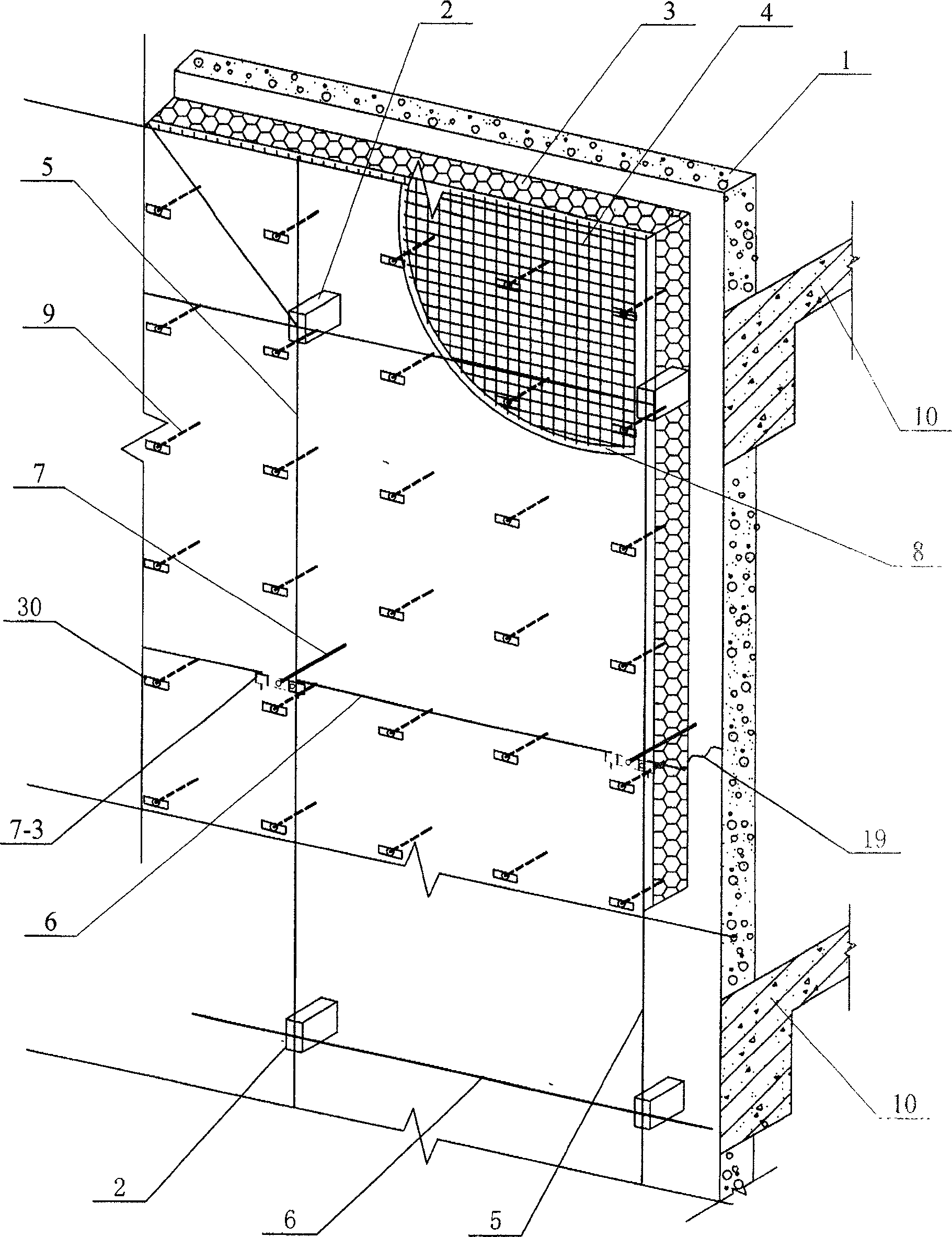
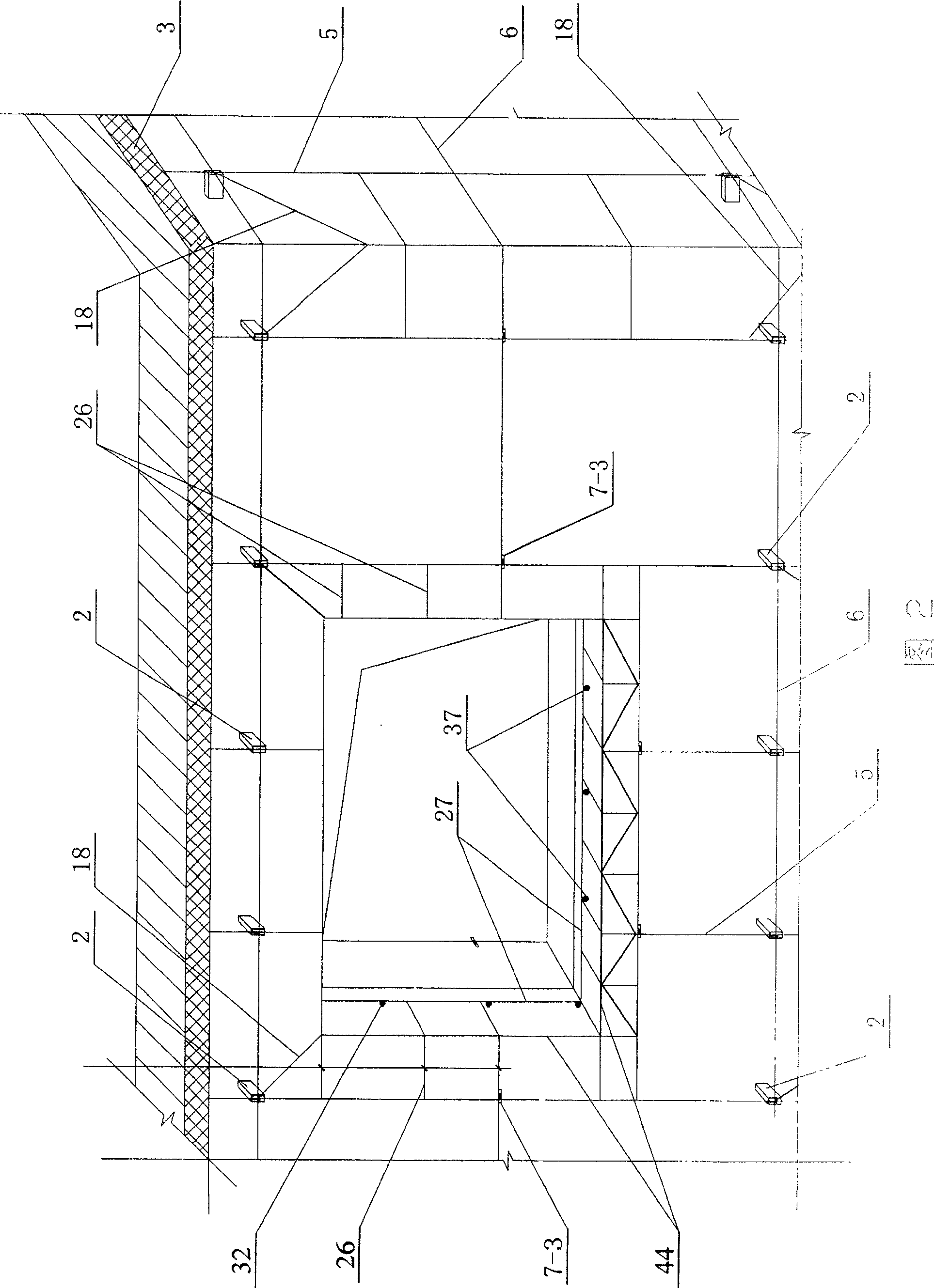
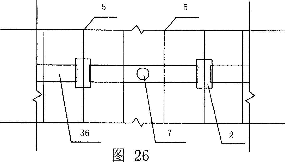
[0013] Specific embodiment one: (see figure 1 , Figure 2, Figure 6, Figure 8, Figure 16, Figure 17, Figure 19 , Figure 20, Figure 27) This embodiment is composed of a base wall 1, a concrete cantilever beam support 2, an insulation layer 3, a metal mesh 4, a vertical steel bar 5, an outer protective layer 8 and a concrete member 10 of the main structure of the building The concrete component 10 of the main structure of the building includes concrete ring beams, concrete beams, concrete pillars, concrete walls, concrete lintels, concrete foundations, concrete balcony slabs, and window side concrete walls connected to the concrete on the upper and lower floors. Column or concrete window sill, the inner end of the concrete cantilever beam support 2 is fixed on the inner or outer surface of the concrete member 10 of the main structure of the building and connected with steel members, or fixed in the base wall 1 of the load-bearing masonry, The outer side of the base wall 1 and the c...

specific Embodiment approach 2

[0015] Specific embodiment 2: In this embodiment, the thermal insulation layer 3 is a polymer mortar prepared with adhesive or plastic expansion nails 9 and fixed on the base wall 1 or on the main structure of the building, or the thermal insulation layer 3 is fixed by sticking nails. , The inner end of the plastic expansion nail 9 is fixed in the base wall 1, and the outer end of the plastic expansion nail 9 is clamped and fixed to the heat preservation board. At present, the commonly used adhesives are adhesives made of polyacrylate emulsion or vinyl acetate-ethylene emulsion and added cellulose, preservatives and other materials to bond with cement and sand to prepare polymer mortar. Polyacrylate emulsions include pure acrylic emulsion, Styrene-acrylic emulsion, silicon-acrylic emulsion, etc., are adhesives with good durability and good bonding performance. When the material of the insulation layer 3 is different, the selected adhesive should match it.

specific Embodiment approach 3

[0016] Specific implementation mode three (see figure 1 , Figure 2, Figure 6-8, Figure 10-17): This embodiment is different from the first embodiment in that an inner and outer pull connection member 7 is added, and the inner end of the inner and outer pull connection member 7 is connected to the base wall 1 Or the concrete members 10 of the main structure of the building are fixedly connected, and the outer ends of the inner and outer pull-connecting pieces 7 are connected and fixed with the vertical steel bars 5 in the outer protective layer 8. The function of the internal and external pull connectors is to reliably tie and fix the vertical steel bars with the base wall or with the concrete members of the main structure of the building at a certain distance on the vertical steel bars. The installation of the internal and external pull connectors can reduce the support of the concrete cantilever beams. The distance between the upper and lower parts reduces thermal bridges and fa...


PUM


Abstract

The invention relates to binding composite heat preservation wall with supporting. The inner end of concrete overhanging girder supporting is fixed in the concrete component or substrate wall of the main construction of the building. And the external end is fixed to vertical reinforcement in the external protection layer. The external side of the substrate wall is insulating layer, and vertical reinforcements are set outside the insulating layer. Metal net is set inside or outside the vertical reinforcements. External protecting layer of cement mortar or pisolite concrete is set outside the insulating layer. The invention has the advantages of save, endurable, good heat preservation and fireproofing ability.

Description

Technical field [0001] The invention relates to an external composite thermal insulation wall of a building. Background technique [0002] The world's energy resources are becoming more and more tense. Building energy conservation is an important issue for the sustainable development of human society. Wall insulation and energy conservation technology is an important part of building energy conservation. The current various wall insulation technologies have the following problems: [0003] 1. The contradiction between safety and insulation has not been solved from the perspective of optimization, that is, the wall insulation with good safety is not good, while the safety of the wall with good insulation is not good, which is manifested in unsafe structure or difficult construction quality control And fire prevention is not safe. Some use steel anchors to connect to the base wall, but this connection is too simple to meet the requirements of the outer wall to withstand greater hor...

Claims


Application Information

Patent Timeline
Patent Type & Authority Patents(China)
IPC IPC(8): E04B1/76E04B2/00E04B1/00E04F13/00
CPCF16B13/00E04B1/7629E04F13/045E04F13/02E04F13/04E04B1/762
Inventor 吴淑环
Owner 吴淑环
Why Eureka
Try Eureka