
Cover tape

a technology of cover tape and tape, applied in the field of cover tape, can solve the problems of poor mounting, affecting the performance of the cover tape, and the peeling rate of the cover tape has also become 0.1 sec/tact or less, and achieves the effects of suppressing the sticking of stored parts, good peeling effect, and excellent transparency

Active Publication Date: 2017-05-30
DENKA CO LTD
View PDF14 Cites 0 Cited by
  • Summary
  • Abstract
  • Description
  • Claims
  • Application Information

AI Technical Summary

Benefits of technology

[0030]The cover tape of the present invention provides a cover tape which maintains a heat seal to a carrier tape made of plastic, such as polystyrene or polycarbonate, and a stable peeling strength even for a long period of time after heat sealing, has excellent transparency, and is capable of greatly suppressing the sticking of stored parts to the cover tape even after prolonged aging in a high-temperature environment, e.g., 60 to 80° C. In addition, according to one embodiment of the present invention, since the peeling layer (C) contains an electrically conductive material, even when storing minute and light-weight electronic parts in a carrier tape, problems during the mounting process, such as electronic parts popping out due to static charging of the cover tape when peeled, can be suppressed.

Problems solved by technology

In recent years, various electronic parts such as capacitors, resistors, IC's, LED's, connectors and switching elements have become remarkably smaller, lighter and thinner, and when there is a large difference between the maximum and minimum values of the peeling strength when peeling a cover tape, i.e., when the variability in the peeling strength is great, the carrier tape will vibrate strongly, which may cause the electronic parts to pop out and result in poor mounting.
Additionally, with the sharp rise in mounting speed, the peeling rate of the cover tape has also become 0.1 sec / tact or less, which is extremely high, so when peeling, the cover tape is subjected to great impact stress.
As a result thereof, when the peeling strength is too strong, the cover tape may break.
On the other hand, when the peeling strength is too weak, the cover tape and carrier tape do not adhere with sufficient strength, so vibrations during transportation or mounting may cause the cover tape to peel off, the electronic parts may fall out, resulting in poor mounting of the electronic parts.
However, even with this method, it was difficult to sufficiently suppress tape breakage when peeling the cover tape from the carrier tape at the above high speed.
Moreover, due to the storage of the cover tape or the transportation or storage environment of the package containing the electronic parts, the temperature and humidity may affect the peeling strength, which may increase or decrease over time and fall outside the appropriate range.
Under these circumstances, electronic parts may become stuck to the heat sealing surface of the cover tape, and poor mounting may occur when mounting the parts on a substrate.
However, they did not take into consideration the sticking of electronic parts to the cover tape when a package storing the parts is stored in a high-temperature environment.
However, while a cover tape with good sealing properties with a carrier tape is discussed in Patent Document 2, there is no discussion regarding any methods for suppressing the variability in the peeling strength.
Moreover, the presence or absence of parts, the direction in which the parts are stored, and defects or bending of leads are sometimes examined with the electronic parts stored in a package.

Method used


Image

  • Cover tape
  • Cover tape

Examples


example 1

[0097][(a-1) m-LLDPE] polymerized using a metallocene was used as a resin ingredient, kneaded at 200° C. using single screw extruder having a 40 mm-bore, and extruded through a T-die at a line rate of 20 m / min to obtain a 40 μm-thick intermediate film. After coating a surface of a 12 μm-thick biaxially drawn polyester film with a polyester anchor coating agent by a gravure method, the above intermediate film [(a-1) m-LLDPE] was applied to obtain a laminated film comprising a biaxially drawn polyester layer and a m-LLDPE layer. Next, the m-LLDPE surface of the film was subjected to a corona treatment, then [(c-1) resin], which was dissolved in cyclohexane, was applied to the corona treated surface by a gravure method such that the thickness after drying would be 0.8 μm to thereby form a peeling layer. Further, as a heat seal layer on the coated surface of the peeling layer, the butyl methacrylate and methyl methacrylate random copolymer [(d-1) acrylic resin] and [(e-1) inorganic fill...

example 2

[0098]As shown in Table 1, the electrically conductive material (c-14) was added to the peeling layer at 400 parts by mass to 100 parts of the resin, and other than the compounding ratio and composition listed in Table 1, a cover tape was produced in the same manner as in Example 1.

example 10

[0103][(a-1) m-LLDPE] polymerized using a metallocene was used as a resin ingredient, kneaded at 200° C. using single screw extruder having a 40 mm-bore, and extruded through a T-die at a line rate of 20 m / min to obtain a 40 μm-thick intermediate film. After coating a surface of a 12 μm-thick biaxially drawn polyester film with a polyester anchor coating agent by a gravure method, the above intermediate film [(a-1) m-LLDPE] was applied to obtain a laminated film comprising a biaxially drawn polyester layer and a m-LLDPE layer. Next, the m-LLDPE surface of the film was subjected to a corona treatment, then [(c-1) resin], which was dissolved in cyclohexane, was applied to the corona treated surface by a gravure method such that the thickness after drying would be 1 μm to thereby form a peeling layer. Further, as a heat seal layer on the coated surface of the peeling layer, the butyl methacrylate and methyl methacrylate random copolymer [(d-1) acrylic resin], [(d-4) electrically conduc...


PUM

PropertyMeasurementUnit
tensile storage modulusaaaaaaaaaa

Abstract

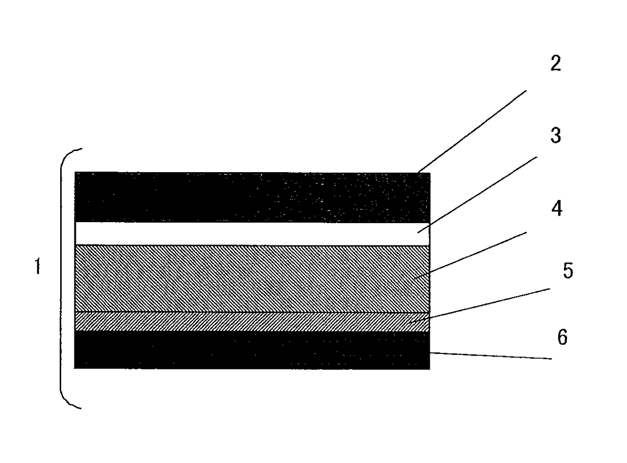
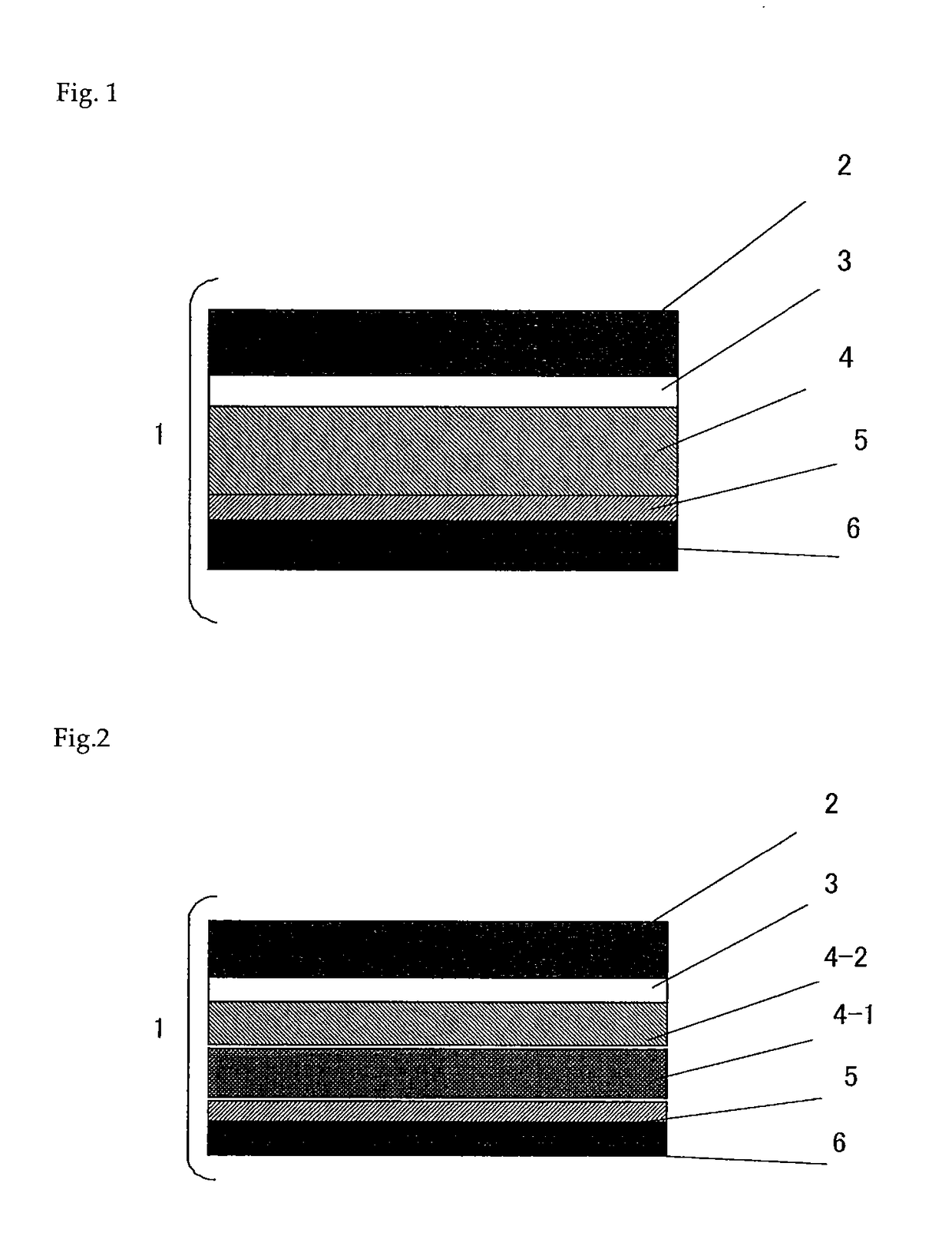
Disclosed is a cover tape which comprises at least a base layer (A), an intermediate layer (B), a peeling layer (C), the primary component of which is a thermoplastic resin, and a heat seal layer (D), the primary component of which is a thermoplastic resin that can be heat sealed to a carrier tape. The tensile storage modulus (c) of the thermoplastic resin that constitutes the peeling layer (C) is within the range of 1×10⁶ Pa to 1×10⁸ Pa. The tensile storage modulus (d) of the thermoplastic resin that constitutes the heat seal layer (D) is within the range of 1×10⁸ Pa to 1×10¹⁰ Pa. The ratio of (c) and (d) satisfies 1×10⁴≧(d) / (c)≧1×10. This kind of cover tape has the appropriate peel strength and sufficiently low fluctuation in peel strength when heat sealed to a thermoplastic resin carrier tape. Therefore, the tape will not tear even under shock caused by high-speed peeling, and sticking of electronic parts does not occur even when set aside for a long period of time of 24 to 72 hours in a high-temperature environment of 60 to 80° C.

Description

TECHNICAL FIELD[0001]The present invention relates to a cover tape for use in packages of electronic parts.BACKGROUND ART[0002]With the miniaturization of electronic devices, electronic parts used therein have also become smaller with higher performance, and parts are being automatically mounted onto printed substrate boards in assembly processes of electronic devices. Electronic parts for surface mounting are stored in a carrier tape on which embossed pockets are consecutively formed according to the shapes of the electronic parts to enable storage thereof. After the electronic parts are stored, a cover tape is applied to the top of the carrier tape as a lid material, and the two ends of the cover tape are continuously heat sealed in the direction of the length using a heated seal bar to make a package. As the material for the cover tape, a laminate of a thermoplastic resin heat seal layer laminated on a substrate of a biaxially drawn polyester film or the like is used.[0003]In rec...

Claims


Application Information

Patent Timeline
Patent Type & Authority Patents(United States)
IPC IPC(8): B32B27/08B32B27/28B32B27/32B32B27/36B32B27/30
CPCB32B27/28B32B27/08B32B27/30B32B27/308B32B27/32B32B27/36Y10T428/31504Y10T428/31786Y10T428/31855Y10T428/31935B32B27/18B65D65/02B65D73/02B65D85/38
Inventor SASAKI, AKIRATOKUNAGA, HISATSUGUFUJIMURA, TETSUO
Owner DENKA CO LTD
Learn More