
Direct integration of feedthrough to implantable medical device housing using a gold alloy

a medical device and gold alloy technology, applied in heat treatment devices, furnaces, therapy, etc., can solve the problems of high cost, weaker joint between ferrule and housing, and change in structure of titanium,

Active Publication Date: 2017-04-04
HERAEUS PRECIOUS METALS GMBH & CO KG
View PDF206 Cites 7 Cited by
  • Summary
  • Abstract
  • Description
  • Claims
  • Application Information

AI Technical Summary

Benefits of technology

The patent text describes a problem in the attachment of a feedthrough device to an implantable medical device housing. The current process of using brazing or soldering to join the feedthrough to the housing causes structural changes in the titanium of the housing and can lead to a weaker joint. Additionally, the current process is costly and not easily repeatable. The patent text proposes a new method using low-temperature brazing to attach the feedthrough to the housing, which may provide a stronger and more reliable joint.

Problems solved by technology

However, the high temperatures employed by such processes heats the titanium of the housing about the perimeter of the opening to levels that cause a structural change in the titanium, commonly referred to as “grain growth”.
This structural change can distort the dimensions of the opening and cause the titanium about the perimeter of the opening to become less rigid, each of which can result in a weaker joint between the ferrule and the housing.
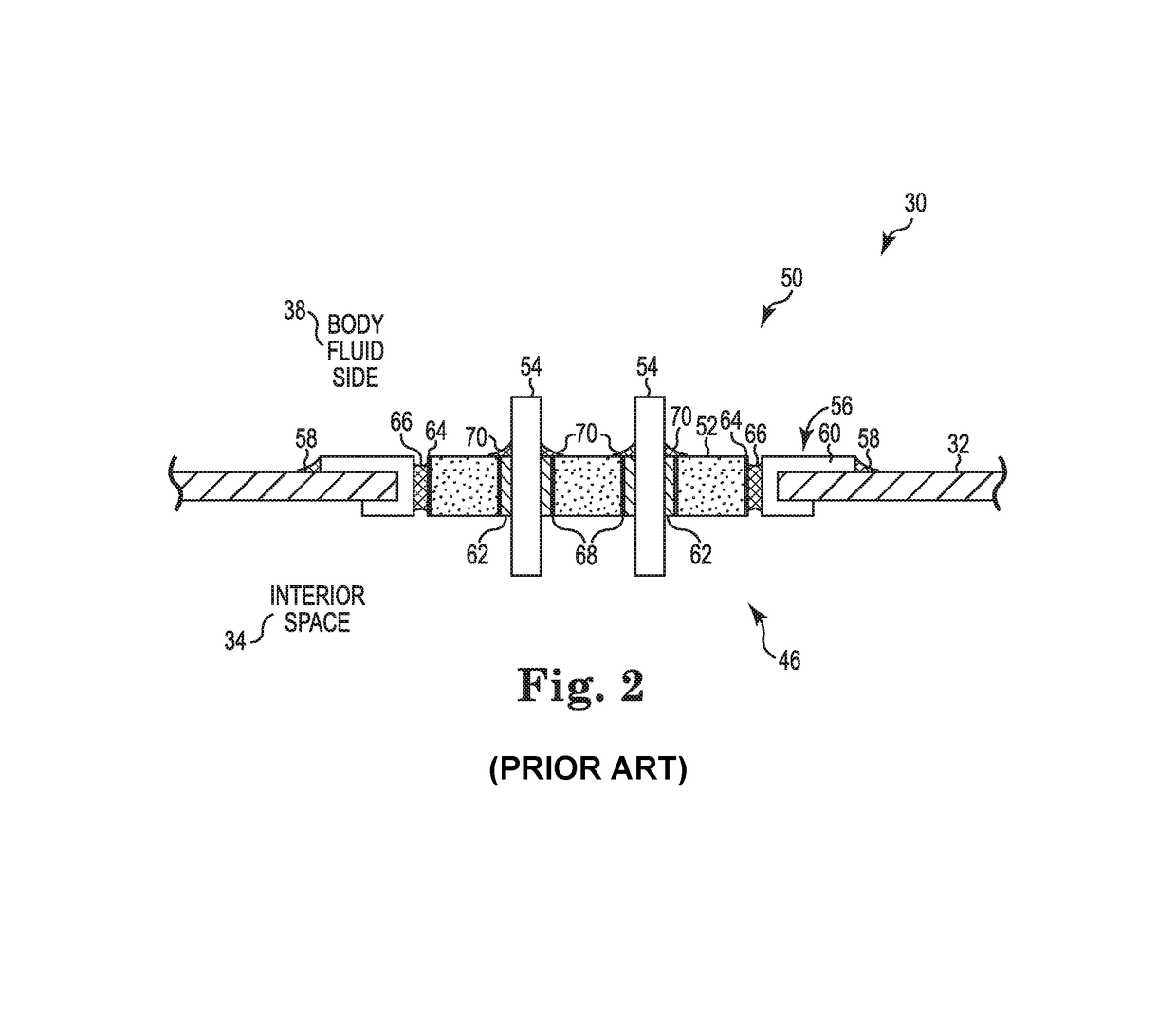
Additionally, machining the ferrule (typically from pure titanium) to provide a high tolerance gap between the ferrule and the insulator (about 10-50 μm) which is necessary to achieve a quality braze joint is demanding and costly.
Furthermore, if the gap is not maintained during the brazing process, or if the brazing process itself is not properly performed, a weak joint may be formed that can lead to premature failure of the implantable device.

Method used


Image

  • Direct integration of feedthrough to implantable medical device housing using a gold alloy
  • Direct integration of feedthrough to implantable medical device housing using a gold alloy
  • Direct integration of feedthrough to implantable medical device housing using a gold alloy

Examples


Embodiment Construction

[0017]In the following Detailed Description, reference is made to the accompanying drawings, which form a part hereof, and in which is shown by way of illustration specific embodiments in which the invention may be practiced. In this regard, directional terminology, such as “top,”“bottom,”“front,”“back,”“leading,”“trailing,” etc., is used with reference to the orientation of the Figure(s) being described. Because components of embodiments can be positioned in a number of different orientations, the directional terminology is used for purposes of illustration and is in no way limiting. It is to be understood that other embodiments may be utilized and structural or logical changes may be made without departing from the scope of the present invention. The following detailed description, therefore, is not to be taken in a limiting sense, and the scope of the present invention is defined by the appended claims.

[0018]It is to be understood that the features of the various exemplary embodi...


PUM

PropertyMeasurementUnit
Temperatureaaaaaaaaaa

Abstract

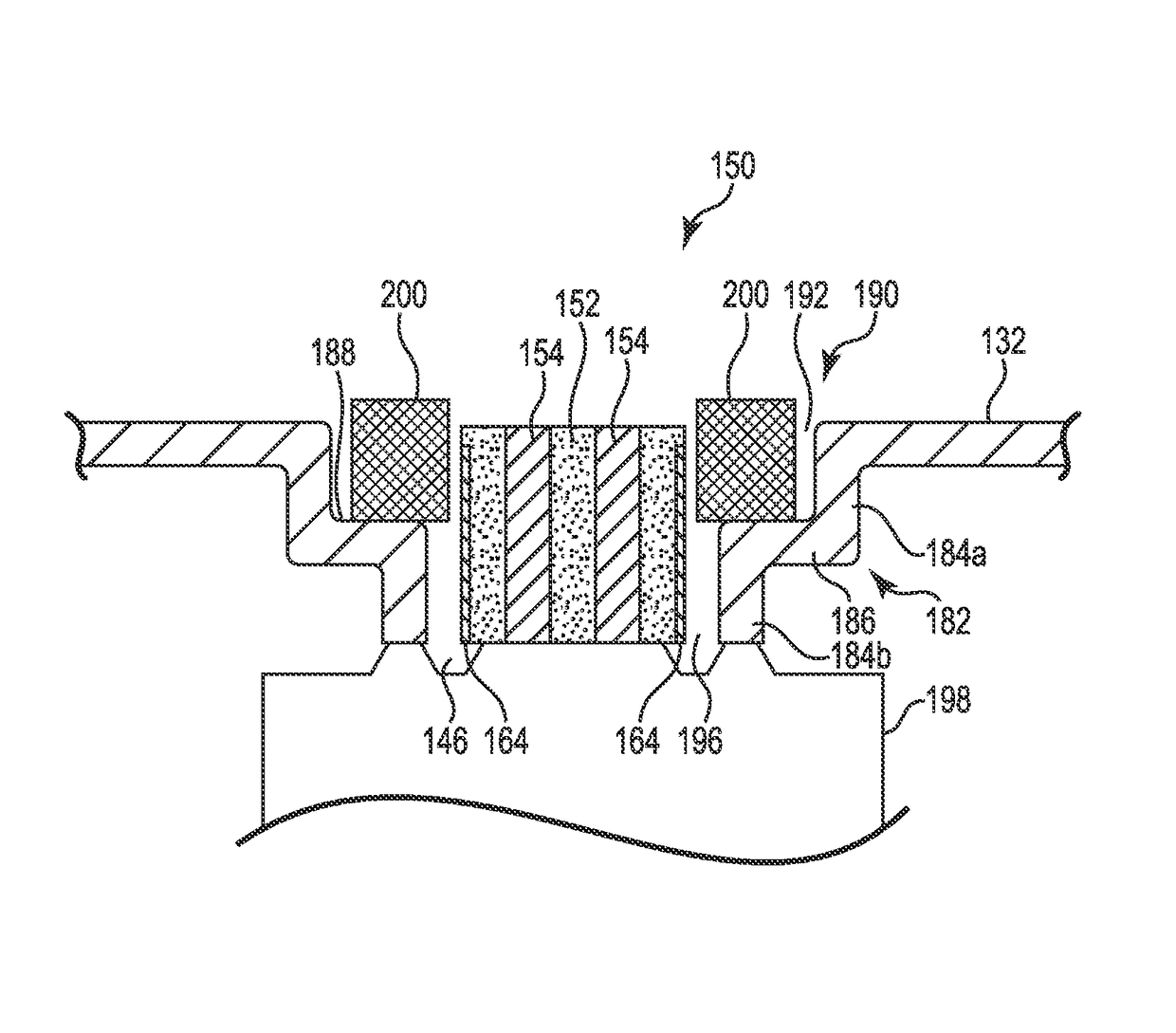
One aspect provides a method of attaching a feedthrough to a titanium housing of an implantable medical device. The method includes providing the housing with a flange forming a recess about an opening through the housing, the opening disposed within the recess. A feedthrough is positioned within the recess so as to form a gap between the flange and an insulator of the feedthrough. A braze preform is then positioned within the recess about the insulator, the braze preform comprising a biocompatible braze material having a melting point less than a β-transus temperature of the titanium of the housing. The preform is melted at a temperature less than the β-transus temperature of the titanium of the housing such that the melted braze material fills at least the gap, and then cooled to form a braze joint which bonds the insulator to the housing and hermetically seals the opening.

Description

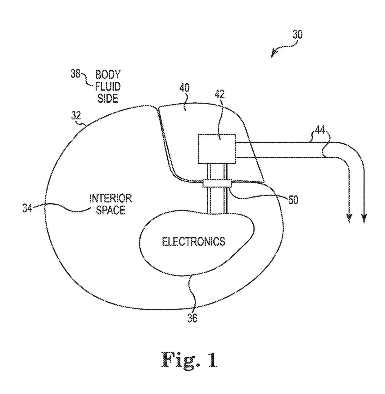
CROSS-REFERENCE TO RELATED APPLICATIONS[0001]This Patent Application is related to Ser. No. 14 / 104,644, filed on even date herewith, entitled “DIRECT INTEGRATION OF FEEDTHROUGH TO IMPLANTABLE MEDICAL DEVICE HOUSING WITH ULTRASONIC WELDING” and Ser. No. 14 / 104,653, filed on even date herewith, entitled “DIRECT INTEGRATION OF FEEDTHROUGH TO IMPLANTABLE MEDICAL DEVICE HOUSING BY SINTERING”, all of which are incorporated herein by reference.BACKGROUND[0002]Implantable medical devices, such as cardiac pacemakers, cardiac defibrillators, and neurostimulators, receive and / or deliver electrical signals to / from portions of the body via sensing and / or stimulating leads. Implantable medical devices typically include a metal housing (typically titanium) having a hermetically sealed interior space which isolates the internal circuitry, connections, power sources, and other device components from body fluids. A feedthrough device (often referred to simply as a feedthrough) establishes electrical ...

Claims


Application Information

Patent Timeline
IPC IPC(8): A61N1/05B23K1/20B23K35/30B23K35/02B23K35/00A61N1/375B23K1/00C21D9/50B23K35/38B23K1/008B23K101/36B23K103/14
CPCA61N1/3754B23K1/0008B23K1/0016B23K1/20B23K35/007B23K35/0222B23K35/0244B23K35/0255B23K35/30B23K35/3013B23K35/38B23K35/383C21D9/50B23K1/008B23K2201/36B23K2203/14B23K35/28C22C5/02B23K2101/36B23K2103/14
Inventor MARKHAM, JACOBHAUSCH, ULRICH
Owner HERAEUS PRECIOUS METALS GMBH & CO KG
Learn More