Copper bonding or superfine wire with improved bonding and corrosion properties
A technology of bonding wires and ultra-fine wires, which can be used in household appliances, transportation and packaging, and other household appliances, etc., and can solve problems such as damage to semiconductors and inappropriate hardness of bonding wires
- Summary
- Abstract
- Description
- Claims
- Application Information
AI Technical Summary
Problems solved by technology
Method used
Image
Examples
example 1
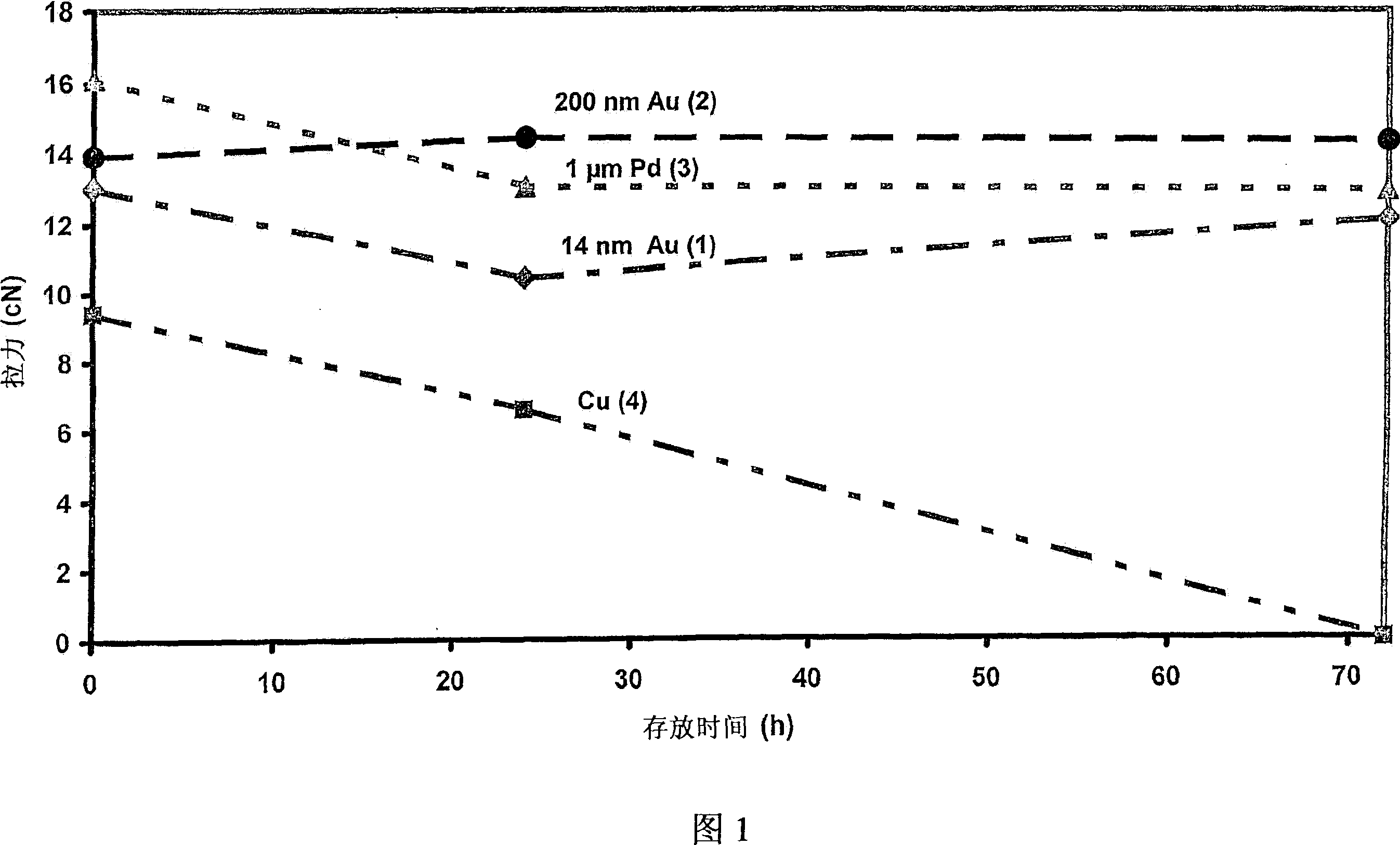
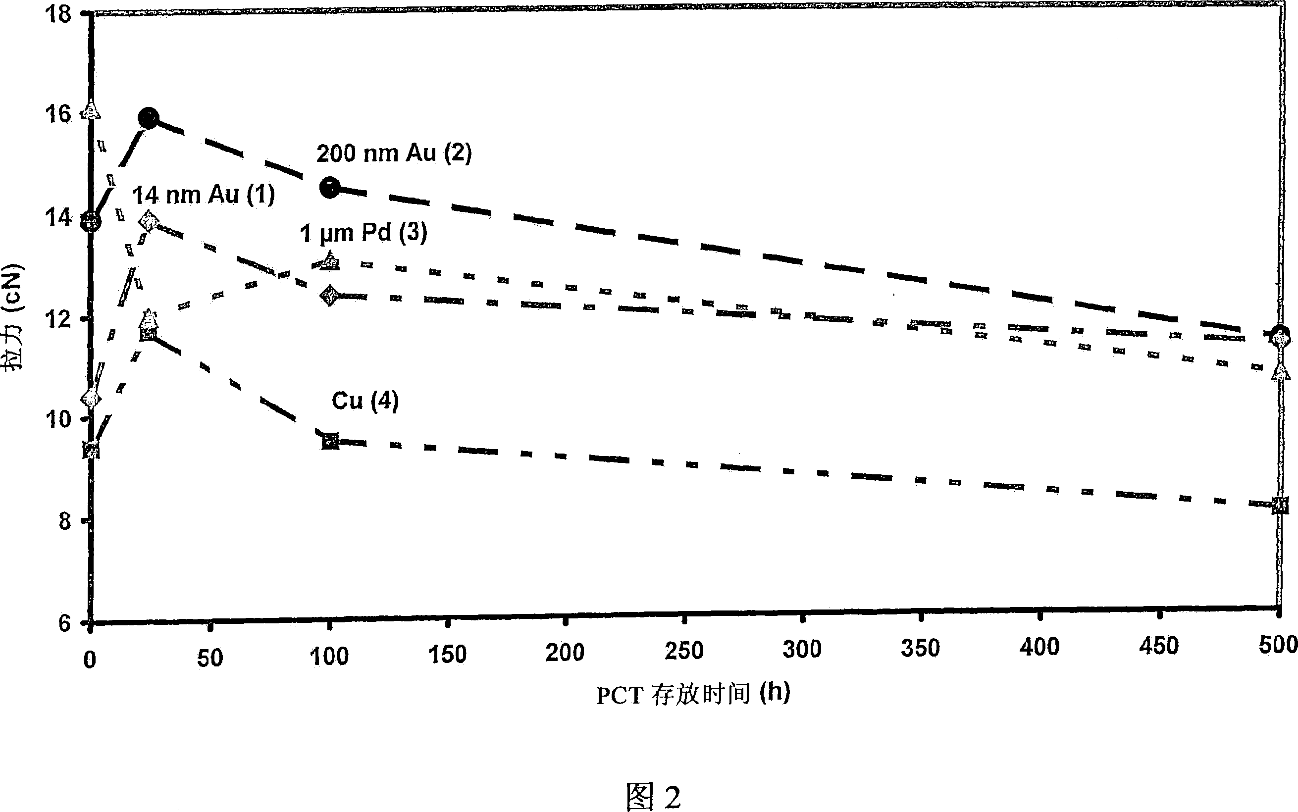
[0039] As can be seen from Figures 1 and 2, the copper bonding wire or ultra-fine wire 1 with a 14nm gold coating according to the present invention has corrosion stability and has a comparable corrosion resistance to bonding wires made of pure gold or pure copper. Loop shear-off force (Loop-Abreisskraft). Thus, the bonding wire according to the present invention has corrosion stability compared to pure copper wire 4 and has improved conductivity and stability compared to gold bonding wires. In the manner of the invention, it is possible to choose from two possibilities, namely: making an alloy, or coating the copper wire with gold, wherein the increased hardness of the gold-copper alloy does not play a role in the bonding process, so , the chip 29 to be bonded will not be damaged when the bonding wire or ultra-fine wire is pressed on the chip.
[0040] Although the gold-copper alloy is considered hard, the balls 21 provided for the bonding process remain soft despite the cor...
example 2
[0042] Electrolytic plating is performed on copper wire with a purity of 99.995%. The output diameter of the copper wire is 250 μm.
[0043] The gold-coated wire was drawn into a wire with a thickness of 25 μm by repeated drawing. In the subsequent annealing treatment, the wire was set to a breaking load of 13 cN and an elongation at break of 14% was obtained ("soft state"). To prevent oxidation of the freshly drawn wire, the wound wire is vacuum welded in a polyethylene (PE) protective film.
[0044]If the gold did not diffuse into the copper (or if the copper did not diffuse into the gold), the wire used here had a coating with a thickness of 20nm. Diffusion blurs the phase boundaries, so the coating thickness is only for a virtual outer layer that doesn't really exist because of the diffusion. The wire thus obtained takes on the color of copper. Therefore, in describing the present invention, the reference to the gold outer layer or coating is not used, but the referenc...
example 3
[0046] The bonding wire 20 described above was stored open and after a predetermined period of time, according to ASTM, 100 Barr Harbor Drive, West Conshohocken, Pennsylvania 19428-2959 and G.G. Harman, "Wire Bonding in Microelectronics", McGraw-Hill 1997, pp. 67ff) Carry out bonding test.
[0047] Joining conditions are as follows:
[0048] The ball-wedge joint (ESEC 3088) has the following joint parameters:
[0049] a) Solder ball terminal (Impact 2000; Force 3000; Time 32; US 80) and
[0050] b) Wedge end (Impact 300; Force 1500; Time 30; US 20)
[0051] The numbers indicate the parameters of the engaging device.
[0052] Use the following substrates:
[0053] 1. Gold-plated Cu-Sn6 substrate
[0054] 2. Aluminum-sprayed silicon chip
[0055] Figure 1 shows the breaking force of the coil. The breaking force can be determined by means of a tensile tester (DAGE BT 22) by the so-called Hook test (cf. literature: MIL STD 883F, June 18, 2004, Microcircuits, Method 2011.7)....
PUM
| Property | Measurement | Unit |
|---|---|---|
| diameter | aaaaa | aaaaa |
| diameter | aaaaa | aaaaa |
| diameter | aaaaa | aaaaa |
Abstract
Description
Claims
Application Information
 - R&D
- Intellectual Property
- Life Sciences
- Materials
- Tech Scout
- Unparalleled Data Quality
- Higher Quality Content
- 60% Fewer Hallucinations
Browse by: Latest US Patents, China's latest patents, Technical Efficacy Thesaurus, Application Domain, Technology Topic, Popular Technical Reports.
© 2025 PatSnap. All rights reserved.Legal|Privacy policy|Modern Slavery Act Transparency Statement|Sitemap|About US| Contact US: help@patsnap.com


