Heat exchanger

a heat exchanger and peripheral wall technology, applied in the field of heat exchangers, can solve the problems of insufficient pitting corrosion prevention effect provided by the sacrificial anode layer, and the peripheral wall pitting corrosion of the heat exchange tube is relatively short, so as to improve the pitting corrosion prevention effect and reduce the corrosion speed

Active Publication Date: 2017-02-28
MAHLE INT GMBH
View PDF8 Cites 1 Cited by
  • Summary
  • Abstract
  • Description
  • Claims
  • Application Information

AI Technical Summary

Benefits of technology

[0008]An object of the present invention is to solve the above-described problem and to provide a heat exchanger which has enhanced pitting corrosion resistance to thereby prolong a period during which occurrence of pitting corrosion is prevented.
[0017]In the heat exchanger of par. 1), when the thickness of the peripheral wall of each heat exchange tube is represented by T [μm], the Zn concentration at the outermost surface of the outer surface layer portion of the heat exchange tube is represented by A [mass %], and the maximum depth of the Zn diffused layer is represented by D [μm], conditions of T≦200, 0.57≦A≦1.5, D / T≦0.55, and 0.0055≦A / D≦0.025 must be satisfied, for the following reasons. Namely, according to the heat exchanger of par. 1), the Zn diffused layer formed in the outer surface layer portion of each heat exchange tube is sacrificially corroded, whereby occurrence of pitting corrosion in the peripheral wall of the heat exchange tube is restrained. As a result of repeated studies performed by the present inventors, it was found that, when the above conditions are satisfied, the maximum corrosion depth at which the progress of corrosion stops or gets saturated can be decreased to a degree corresponding to the thickness of the peripheral wall of each heat exchange tube, and that the pitting corrosion prevention effect is maintained for a long period of time because of the decreased maximum corrosion depth, as well as the decreased corrosion speed attained by setting the upper limits of the amounts of Cu, Fe, and Si contained in the alloy used to form the heat exchange tubes. In the case where the thickness T [μm] of the peripheral wall of each heat exchange tube is decreased to 200 or less in order to decrease the weight of the heat exchange tube, it is possible to decrease the maximum corrosion depth at which the progress of corrosion stops or gets saturated, by setting the ratio of the Zn concentration A [mass %] at the outermost surface of the outer surface layer portion of the heat exchange tube to the maximum depth D [μm] of the Zn diffused layer to fall within a proper range, and by setting the ratio of the maximum depth D [μm] to the thickness T [μm] to fall within a proper range.
[0019]In the heat exchanger of par. 2), the spontaneous potential of the Zn diffused layer is set to be 100 to 150 mV lower than that of the inner portion of the peripheral wall of the heat exchange tube, located on the inner size of the Zn diffused layer, in order to further enhance the pitting corrosion prevention effect achieved by sacrificial corrosion of the Zn diffused layer.
[0020]According to the heat exchangers of pars. 1) and 2), the maximum corrosion depth at which the progress of corrosion stops can be decreased to a degree corresponding to the thickness of the peripheral wall of each heat exchange tube, and the corrosion speed can be decreased. As a result, the pitting corrosion prevention effect achieved by sacrificial corrosion of the Zn diffused layer can be maintained for a long period of time.

Problems solved by technology

Incidentally, since such a condenser for a car air conditioner is used in a corrosive environment, pitting corrosion occurs in the peripheral walls of the heat exchange tubes within a relatively short period of time.
Therefore, the pitting corrosion prevention effect provided by the sacrificial anode layer may be insufficient.

Method used


Image

  • Heat exchanger
  • Heat exchanger
  • Heat exchanger

Examples


examples

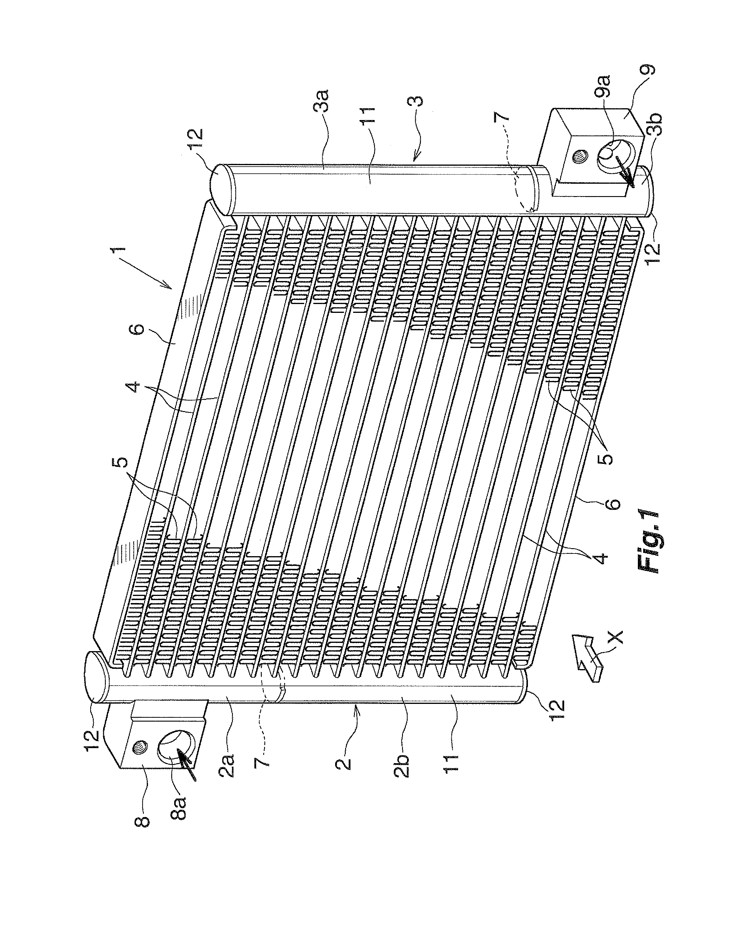
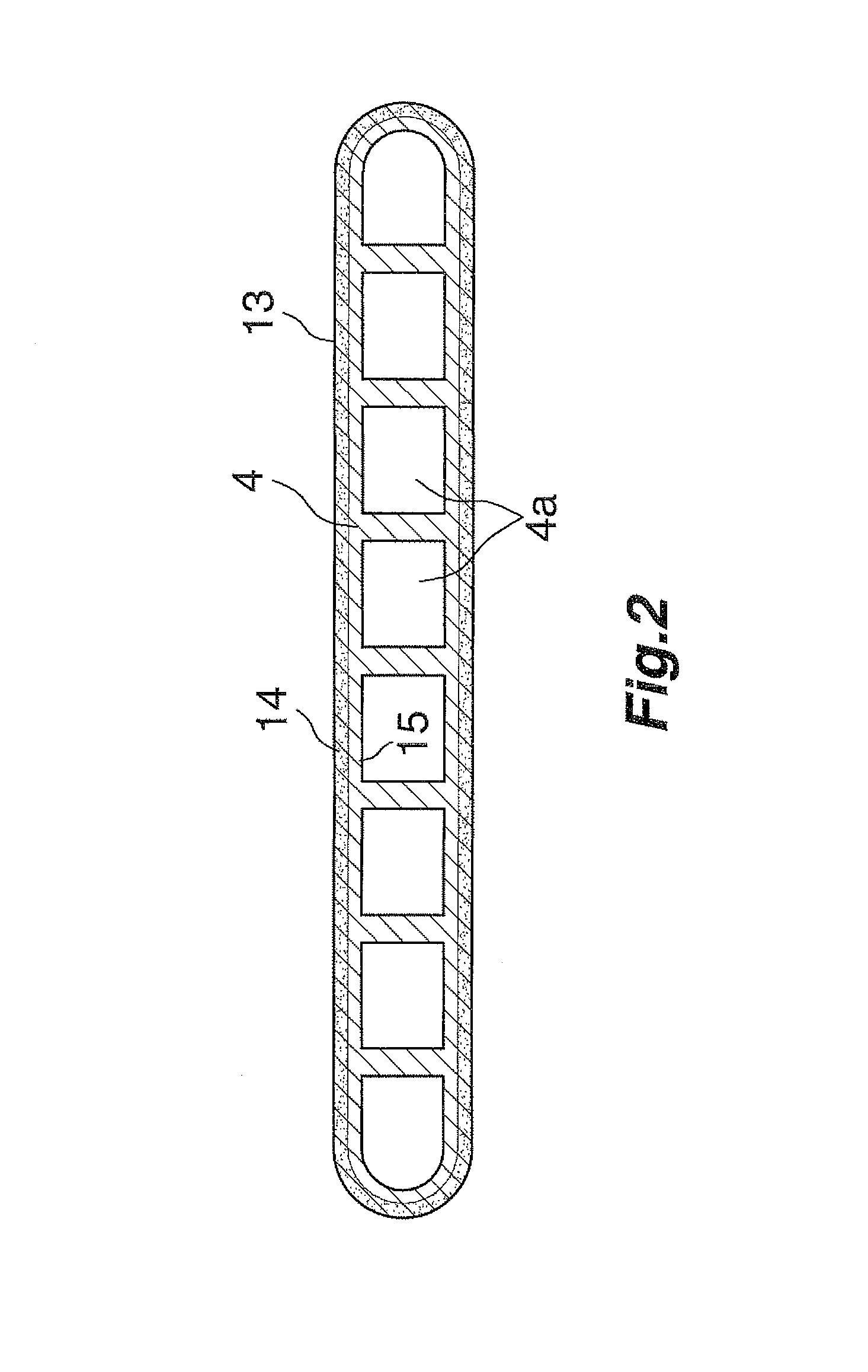
[0040]Heat exchange tubes formed of extrudate, having a cross-sectional shape shown in FIG. 2, and having a width of 12 mm, a length of 650 mm, and a largest peripheral wall thickness (the thickness of the thickest portion of the peripheral wall) of 200 μm were formed through use of an alloy containing Mn in an amount of 0.25 mass %, the balance being Al and unavoidable impurities. The alloy did not contain Cu, and contained Fe in an amount of 0.2 mass % or less and Si in an amount of 0.2 mass % or less. Cu, Fe, and Si are unavoidable impurities. Also, corrugated fins were formed through use of a brazing sheet having a thickness of 70 μm. The brazing sheet was composed of an aluminum core, and skin layers formed of aluminum brazing material and covering the opposite surfaces of the core. The core contained Si in an amount of 0.45 mass %, Mn in an amount of 1.5 mass %, Zn in an amount of 1.5 mass %, the balance being Al and unavoidable impurities. The brazing material contained Si in...


PUM

PropertyMeasurementUnit
thicknessaaaaaaaaaa
thicknessaaaaaaaaaa
particle sizeaaaaaaaaaa

Abstract

Heat exchange tubes of a heat exchanger are formed of an alloy containing Mn (0.2 to 0.3 mass %), Cu (0.1 mass % or less), and Fe (0.2 mass % or less), the balance being Al and unavoidable impurities. A Zn diffused layer is formed in an outer surface layer portion of the peripheral wall of each heat exchange tube. T≦200, 0.57≦A≦1.5, D / T≦0.55, and 0.0055≦A / D≦0.025 are satisfied, where T is the thickness [μm] of the peripheral wall of the heat exchange tube, A is the Zn concentration [mass %] at the outermost surface of the outer surface layer portion, and D is the maximum depth [μm] of the Zn diffused layer. The spontaneous potential of the Zn diffused layer is lower than that of a portion of the peripheral wall located on the inner side of the Zn diffused layer.

Description

BACKGROUND OF THE INVENTION[0001]The present invention relates to a heat exchanger, and more particularly to a heat exchanger which is used as a condenser for a car air conditioner, an evaporator for a car air conditioner, a heater core for a car air conditioner, or a radiator, each of which is mounted on a vehicle such as an automobile.[0002]In this specification and claims, the term “aluminum” encompasses aluminum alloys in addition to pure aluminum. Also, materials represented by chemical symbols represent pure materials.[0003]In this specification, the term “spontaneous potential” of a material refers to the electrode potential of the material in an acidic (pH: 3) aqueous solution of 5% NaCl with respect to a saturated calomel electrode (S.C.E.), which serves as a reference electrode.[0004]A widely used condenser for a car air conditioner includes a pair of an aluminum header tanks disposed apart from each other such that their longitudinal direction coincides with the vertical ...

Claims


Application Information

Patent Timeline
Patent Type & Authority Patents(United States)
IPC IPC(8): F28D21/00F28F19/06F28D1/053B32B15/01B22F1/00C21C5/00C22C21/00F28F21/08C22C21/02B22F1/105
CPCC22C21/00C22C21/02F28D1/05333F28F19/06F28F21/084B22F1/007B32B15/01C21C5/005F28D2021/0084F28D2021/0085F28D2021/0094F25B39/04F28F21/08B22F1/105B32B15/016B32B15/017C22C21/10B23K1/0012B23K35/282B23K35/3605B23K35/362B23K35/025B23K2103/10B23K1/008B23K1/012B23K1/19B23K1/20B23K1/203B23K2101/14B23K2101/35
Inventor IKAWA, YOUHEITERADA, TAKASHIOTSUKI, HIROSHI
Owner MAHLE INT GMBH
Why Eureka
Try Eureka