Solid electrolyte membrane, fuel battery cell, and fuel battery

a technology of solid electrolyte membrane and fuel battery, which is applied in the manufacture of cell components, final product manufacturing, electrochemical generators, etc., can solve the problems of insufficient strength of solid electrolyte layers less than 0.3 mm thick, and achieve low internal resistance, strong electromotive force, and mechanical strength.

Active Publication Date: 2016-04-19
SANTOKU CORP +1
View PDF14 Cites 1 Cited by
  • Summary
  • Abstract
  • Description
  • Claims
  • Application Information

AI Technical Summary

Benefits of technology

[0007]It is an object of the present invention to provide a solid electrolyte membrane useful in achieving strong electromotive force and excellent current-voltage characteristics of fuel batteries, as well as a fuel battery cell with this membrane, and methods for producing these.
[0008]It is another object of the present invention to provide a solid electrolyte membrane which is useful in achieving strong electromotive force and excellent current-voltage characteristics of fuel batteries, in particular, which inhibits voltage drop and has excellent load characteristics, as well as a fuel battery cell with this membrane, and methods for producing these.
[0009]The present inventors have made intensive researches in the technology of forming a solid electrolyte membrane with its denseness maintained, to find out that a solid electrolyte membrane may be made extremely thinner than the conventional ones with its mechanical strength maintained, by employing a substrate of a particular structure. By the use of a solid electrolyte membrane of such a structure in a fuel battery, the present inventors could achieve sufficiently high open circuit voltage (OCV) and excellent current-voltage characteristics, to thereby complete the present invention.
[0011]By using this substrate, the internal resistance of the solid electrolyte membrane may be kept low, while the mechanical strength of the dense solid electrolyte membrane may be improved.
[0033]In the present invention, the solid electrolyte layer may preferably contain one of the metal oxides selected from the group consisting of NaCo2O4, LaFe3Sr3O10, Bi4Sr14Fe24O56, NaLaTiO4, RbLaNb2O7, KLaNb2O7, and Sr4Co1.6Ti1.4O8(OH)2.xH2O. These metal oxides develop superior hydroxide ion conductivity when subjected to reduction-hydrationtreatment. In this case, the catalyst layer may also preferably contain these metal oxides, on which precious metal is carried. When both the solid electrolyte layer and the catalyst layer contain the same kind of metal oxide, the interface between the two can be continuous, which causes sufficiently low internal resistance of a laminate of the solid electrolyte layer and the catalyst layer.
[0035]According to the present invention, the solid electrolyte membrane, employing the particular substrate with a plurality of openings as a structural member, may be made thinner than the conventional ones, with its mechanical strength maintained, and its solid electrolyte layer may be given low internal resistance with its denseness maintained, so that a fuel battery having a sufficiently strong electromotive force may be produced.

Problems solved by technology

Patent Publication 1 teaches that a solid electrolyte layer of less than 0.3 mm thick tends to be insufficient in strength.

Method used


Image

  • Solid electrolyte membrane, fuel battery cell, and fuel battery
  • Solid electrolyte membrane, fuel battery cell, and fuel battery
  • Solid electrolyte membrane, fuel battery cell, and fuel battery

Examples


first embodiment

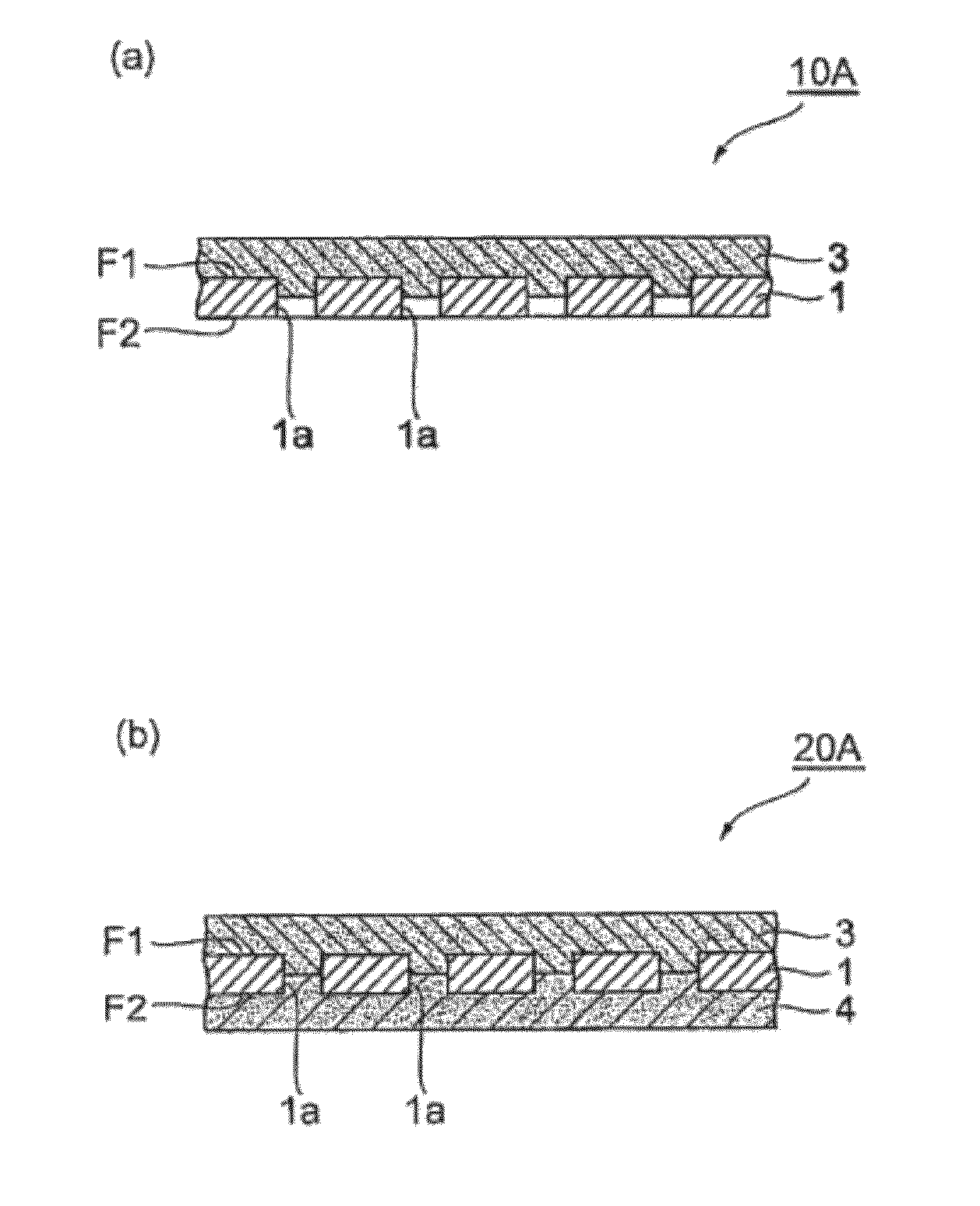
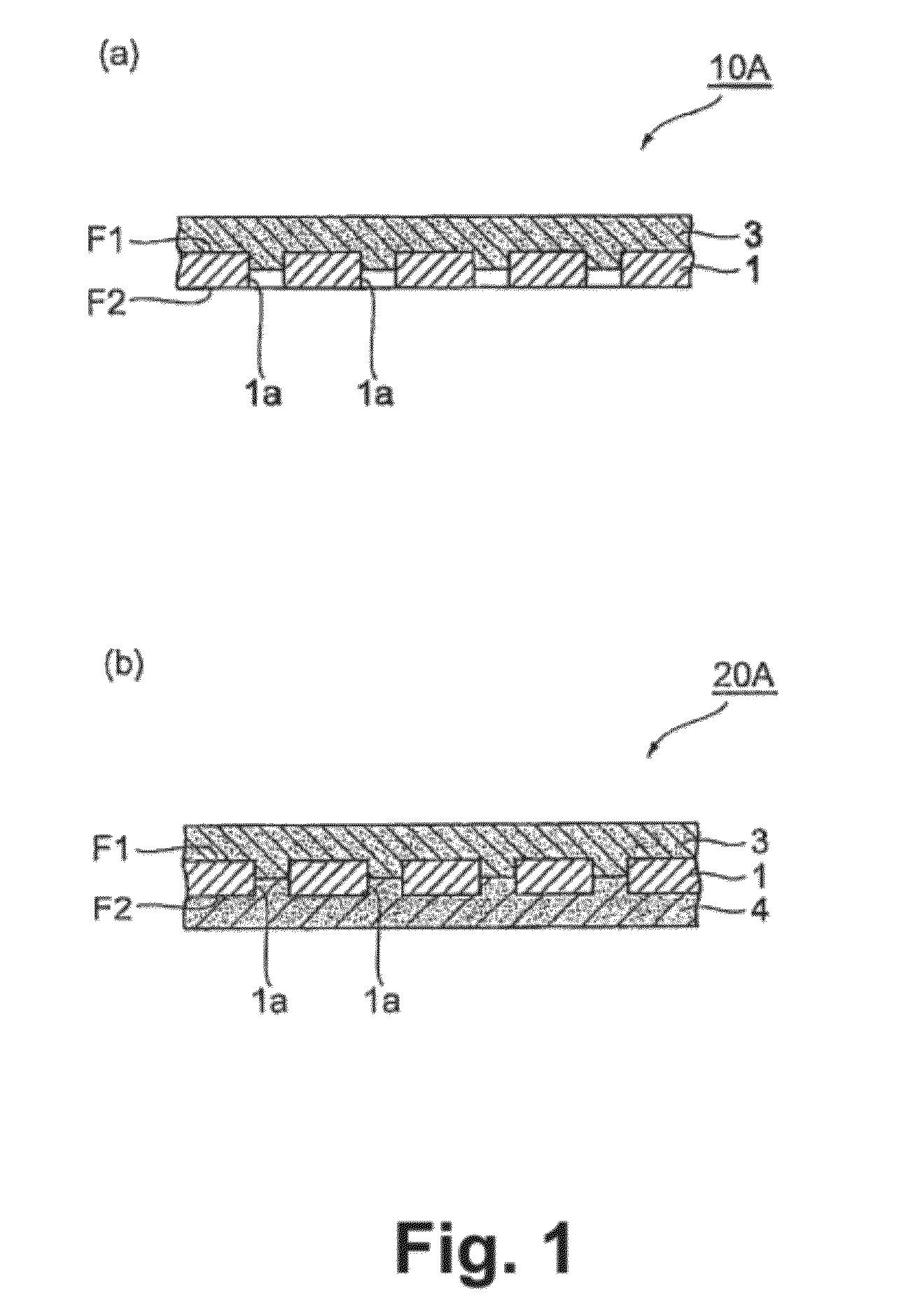
[0076]The fuel battery cell 20A shown in FIG. 1(b) has catalyst layer 4 on the face F2, where the solid electrolyte layer 3 is not provided, of the solid electrolyte membrane 10A. As can be seen from FIG. 1(b), the solid electrolyte layer 3 is in contact with the catalyst layer 4 in the openings 1a of the substrate 1. As mentioned above, the contact portion between the solid electrolyte layer 3 and the catalyst layer 4 in each of the openings 1a independently functions as a fuel battery so that the cell as a whole can be regarded as parallel fuel batteries. If the contact portion in one of the openings 1a fails to exhibit the battery performance for some reason, the remaining, many contact portions can maintain the battery performance of the overall cell, so that drastic improvement in durability is realized.

[0077]Fabrication of the fuel battery cell 20A starts with preparation of the solid electrolyte membrane 10A shown in FIG. 1(a), and a paste or slurry for forming the catalyst l...

second embodiment

[0082]The fuel battery cell 20B shown in FIG. 3(b) has catalyst layer 5 formed on one of the faces of the solid electrolyte membrane 10B, such that the solid electrolyte layer 3 and the catalyst layer 5 contact with each other directly.

[0083]Fabrication of the fuel battery cell 20B starts with preparation of the solid electrolyte membrane 10B shown in FIG. 3(a), and a paste or slurry for forming the catalyst layer (second slurry) in the same way as in the first embodiment. The paste or slurry for forming the catalyst layer is applied to one of the faces of the solid electrolyte membrane 10B, and the solid electrolyte membrane 10B with the slurry applied is dried and / or baked, to thereby obtain fuel battery cell 20B. Here, the fuel battery cell 20B may optionally be compacted by pressing at 40 to 60 MPa for 1 to 30 minutes. However, only the pressing during fabrication of the solid electrolyte membrane 10B may suffice. In this fuel battery cell 20B, the boundary between the solid ele...

example 1

[0121]A fuel battery cell was fabricated using punched metal (26 μm thick, pore size φ60 μm, porosity 32%) as a substrate, and subjected to an electricity generation test. A micrograph of the punched metal taken under a scanning electron microscope (manufactured by JEOL LTD., JSM-6300) is shown in FIG. 5. The thickness of the obtained solid electrolyte membrane (the total of the thicknesses of the electrolyte NaCo2O4 and the substrate) was 47 μm. While the temperature upon measurement of the part where the sample was mounted was kept at 75° C., the open circuit voltage (OCV) was measured. The result is shown in Table 1. A current-voltage curve at 75° C. is shown in FIG. 7.


PUM


Abstract

Provided are a solid electrolyte membrane useful in achieving strong electromotive force in a fuel battery, and a fuel battery cell produced with this membrane. The solid electrolyte membrane includes a substrate made of a sheet material and having a plurality of openings penetrating the substrate in its thickness direction, and a solid electrolyte layer provided on at least one of the faces of the substrate. The fuel battery cell includes a solid electrolyte membrane having the solid electrolyte layer on one of the faces of the substrate, and a catalyst layer containing a precious metal and provided on the other of the faces of the substrate, with the solid electrolyte layer and the catalyst layer being in contact with each other in the openings of the substrate.

Description

CROSS REFERENCE TO RELATED APPLICATIONS[0001]This application is a National Stage of International Application No. PCT / JP2011 / 054596 filed Mar. 1, 2011, claiming priority based on Japanese Patent Application No. 2010-045778, filed Mar. 2, 2010, the contents of all of which are incorporated herein by reference in their entirety.FIELD OF ART[0002]The present invention relates to solid electrolyte membranes, fuel battery cells, and methods of producing these. The present invention also relates to fuel batteries having the fuel battery cell.BACKGROUND ART[0003]Patent Publication 1 discloses an invention relating to a fuel battery containing a layered metal oxide NaCo2O4 as a solid electrolyte. The object of this invention is to obtain strong electromotive force even at about 20 to 80° C., i.e., such low temperatures as from about room temperature, without using deleterious substances or platinum.[0004]Patent Publication 1 teaches that a solid electrolyte layer of less than 0.3 mm thick ...

Claims


Application Information

Patent Timeline
Patent Type & Authority Patents(United States)
IPC IPC(8): H01M8/10H01M8/12H01M4/88H01M4/92
CPCH01M8/1246H01M4/881H01M4/92H01M8/1213H01M8/10H01M8/12H01M2008/1293Y02E60/521Y02E60/525Y02P70/56Y02E60/50Y02P70/50
Inventor MATSUDA, MOTOFUMIMUROTA, TADATOSHITAKEGUCHI, TATSUYAUEDA, WATARU
Owner SANTOKU CORP
Why Eureka
Try Eureka