
Glass compositions for gaskets of apparatuses operating at high temperatures and assembling method using them

a technology of glass compositions and gaskets, applied in the field of glass compositions, can solve the problems of high temperature corrosion or evaporation problems, complex industrial development of this type of vitroceramic glasses, and delicate development of heat treatments for vitroceramic glasses, so as to achieve the optimal balance between flexibility and rigidity, and satisfy the effect of rigidity

Active Publication Date: 2016-04-12
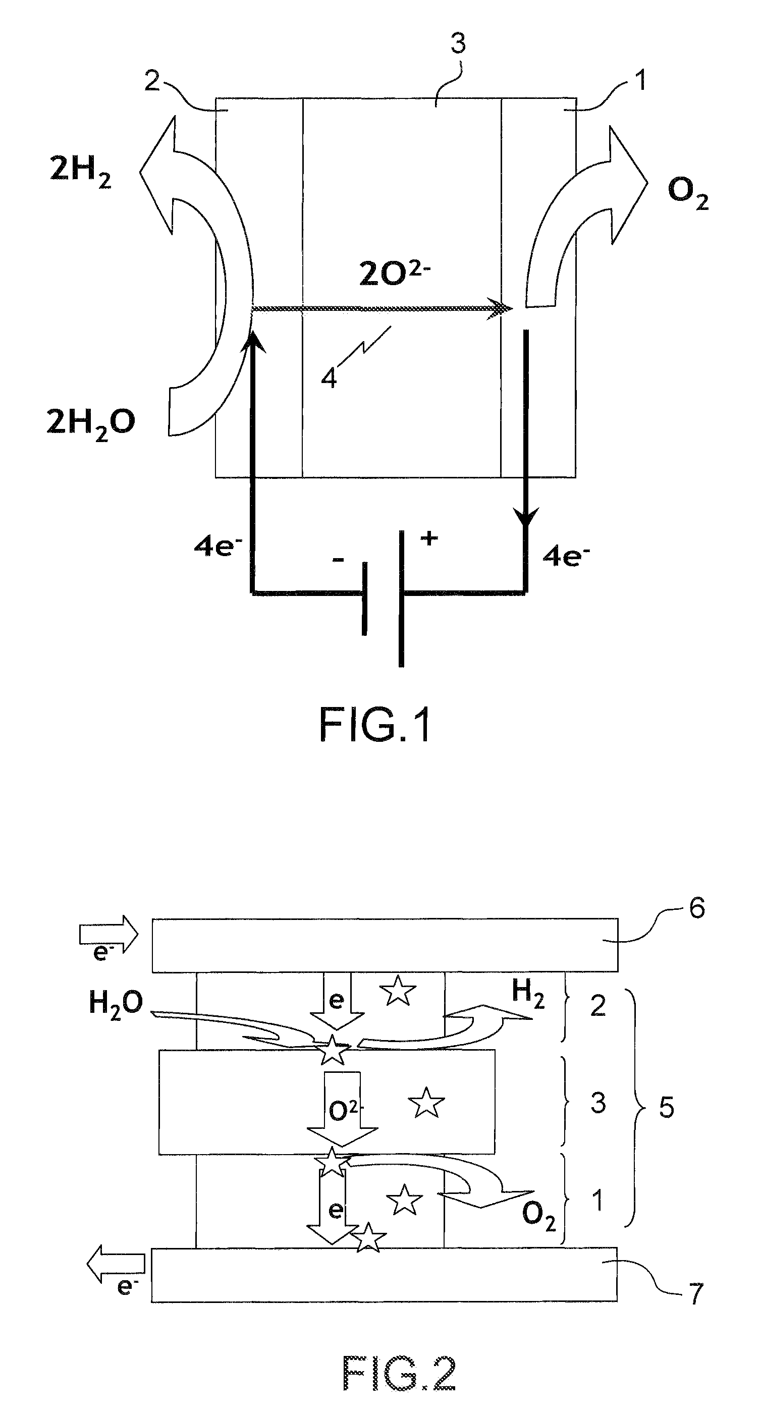
COMMISSARIAT A LENERGIE ATOMIQUE ET AUX ENERGIES ALTERNATIVES
View PDF10 Cites 2 Cited by
  • Summary
  • Abstract
  • Description
  • Claims
  • Application Information

AI Technical Summary

Benefits of technology

The invention provides glass compositions that have a unique viscosity range and can adapt to different materials while maintaining a satisfactory rigidity to support pressure differences. This results in an optimal balance between flexibility and rigidity.

Problems solved by technology

However, development of the formulations and of the heat treatments for vitroceramic glasses remains delicate since the junction material changes over time, with modification of the crystalline phases and because of the creation of interfaces between the materials in contact.
Industrial development of this type of vitroceramic glasses therefore remains complex.
The delicate point lies in the presence of a glassy phase in a large amount which may pose high temperature corrosion or evaporation problems.
With these compositions, it is possible to accommodate the large TEC differences, but the formulations developed in this document do not seem to be sufficiently resistant from a mechanical point of view, exactly because of this too large fluidity of the glass, in order to be able to maintain the seal against the imposed pressure differences.
It emerges from the foregoing that presently there does not exist any glass composition which is satisfactory for a use in seal gaskets for apparatuses operating at high temperature such as high temperature electrolyzers or high temperature fuel cells.

Method used


Image

  • Glass compositions for gaskets of apparatuses operating at high temperatures and assembling method using them
  • Glass compositions for gaskets of apparatuses operating at high temperatures and assembling method using them
  • Glass compositions for gaskets of apparatuses operating at high temperatures and assembling method using them

Examples


example 1

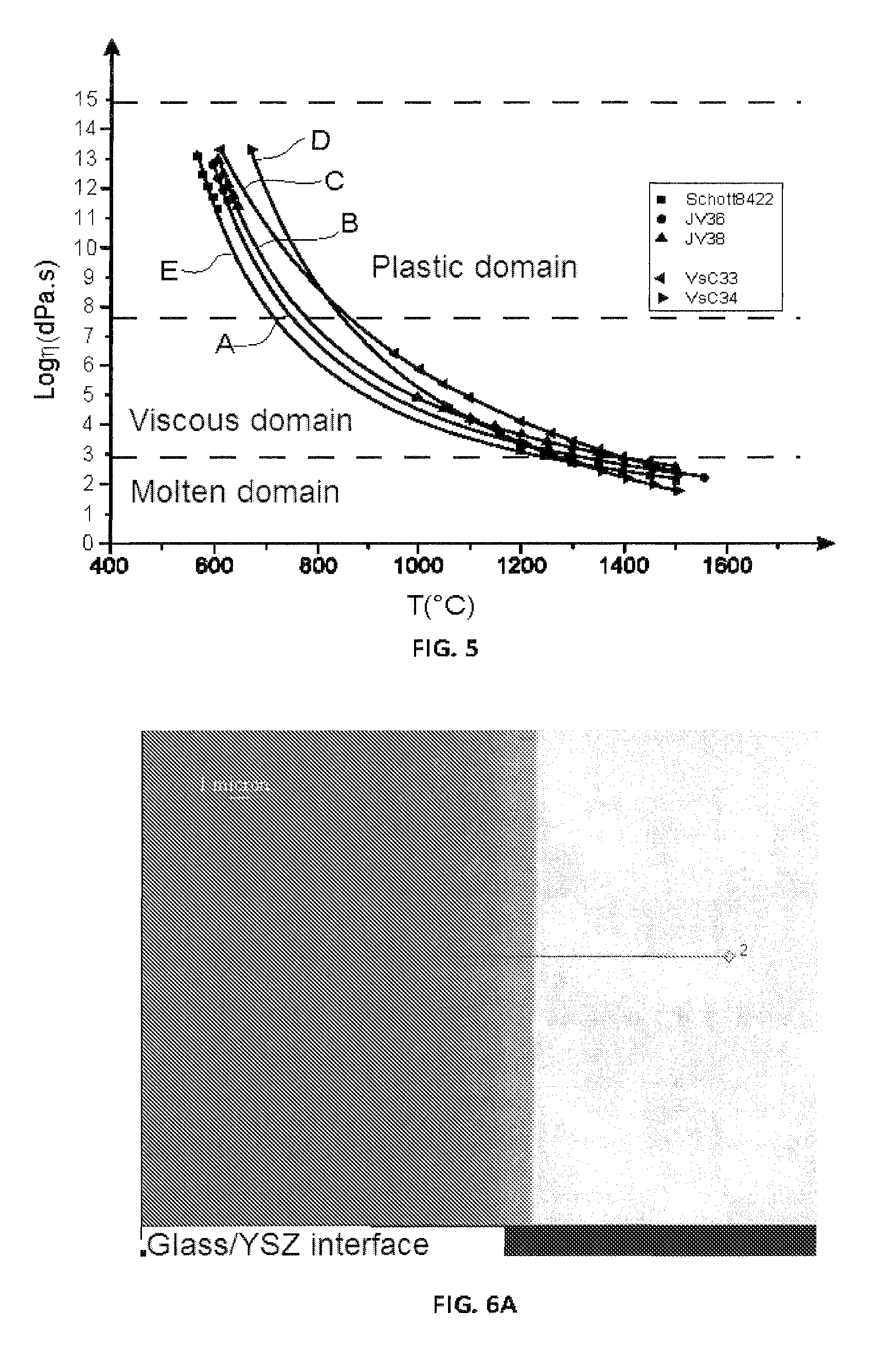
[0257]In this example, measurements of viscosity are carried out for both glasses (A) according to the invention described above, designated as > and > and for the two glasses (B) according to the invention described below, designated as > and > and for the comparative glass Schott® 8422.

[0258]These measurements were carried out in two ranges of temperatures, (550° C.-700° C.) and (1,000° C.-1,500° C.) which were correlated through a law of the VFT type

[0259](log⁢⁢η=A+BT-T0).

[0260]In FIG. 5 in which the plastic, viscous and molten domains of the glasses are illustrated, it is noted that in the range from 700° C. to 850° C. which is the operating range currently used in apparatuses such as high temperature electrolyzers or high temperature fuel cells, the glasses > and > according to the invention have a visco-plastic behavior giving the gasket an optimum combination of flexibility and rigidity.

[0261]This is also the case of the glasses VsC33 and VsC34.

[0262]In particular, at 800° C....

example 2

[0263]In this example, the interactions of the glass compositions according to the invention and of the Schott® 8422 glass with various materials making up an electrolyzer at the operating temperature, i.e. 800° C., and for a period of 100 hours in an oxidizing atmosphere, are investigated.

[0264]These tests are conducted in the laboratory with samples of materials representative of the electrolyzer, on which a small amount of glass slurry, paste is positioned, applied in the same way as for the tests on the prototypes of electrolyzers. The glass / metal and glass / ceramic samples are treated in air in a muffle furnace.

[0265]The interface is then observed with a scanning electron microscope (SEM).

[0266]Study of the Interaction of the > Glass with the > Ceramic for 100 Hours at 800° C. in an oxidizing atmosphere.

[0267]FIG. 6A is a photograph taken with an SEM of the interface between the > glass according to the invention and the YSZ ceramic after 100 hours of operation at 800° C.

[0268]I...

example 3

[0278]In this example, seal tests are conducted by measuring the pressure drop on the Schott® 8422 glass and on the > glass according to the invention.

[0279]The assembly for exerting pressure used for these measurements is schematized in FIG. 7.

[0280]The assembly essentially consists of 3 portions:[0281]a metal sole (71) for example made of steel;[0282]a ceramic disk or sole (72) simulating the cell;[0283]a metal bell (73).

[0284]As this may be seen in FIG. 8, the test gasket is the internal gasket (74), deposited in the groove formed by a portion of the metal sole and the flank (75) of the ceramic disk. The so-called constraint gasket (76) allows the upper portion of the assembly to be sealed and pressure to be applied for the seal test of the internal gasket (74).

[0285]The assembly of FIG. 7 is positioned in a circuit for applying the pressure fed by an argon circuit (77) comprising adjustment (78), purging (79) and isolating (80) valves and a sensor (81) (see FIG. 9).

[0286]The ope...


PUM

PropertyMeasurementUnit
temperatureaaaaaaaaaa
glass transition temperatureaaaaaaaaaa

Abstract

A glass composition, characterized in that it is selected from the group consisting of: a glass composition (A) with the following molar percentages: 70 to 76% of SiO2, 7 to 8% of B2O3, 5 to 6% of Al2O3, and 10 to 17% of Na2O; and a glass composition (B) with the following molar percentages: 63 to 76% of SiO2, 5 to 12% of ZrO2, 0 to 12% of B2O3, 0 to 2% of La2O3, 11 to 14% of Na2O, and 3 to 5% of K2O. The glass composition can be used in a method for assembling parts, in particular for a method of manufacturing high-temperature electrolyzers (HTEs) or high-temperature fuel cells (SOFCs).

Description

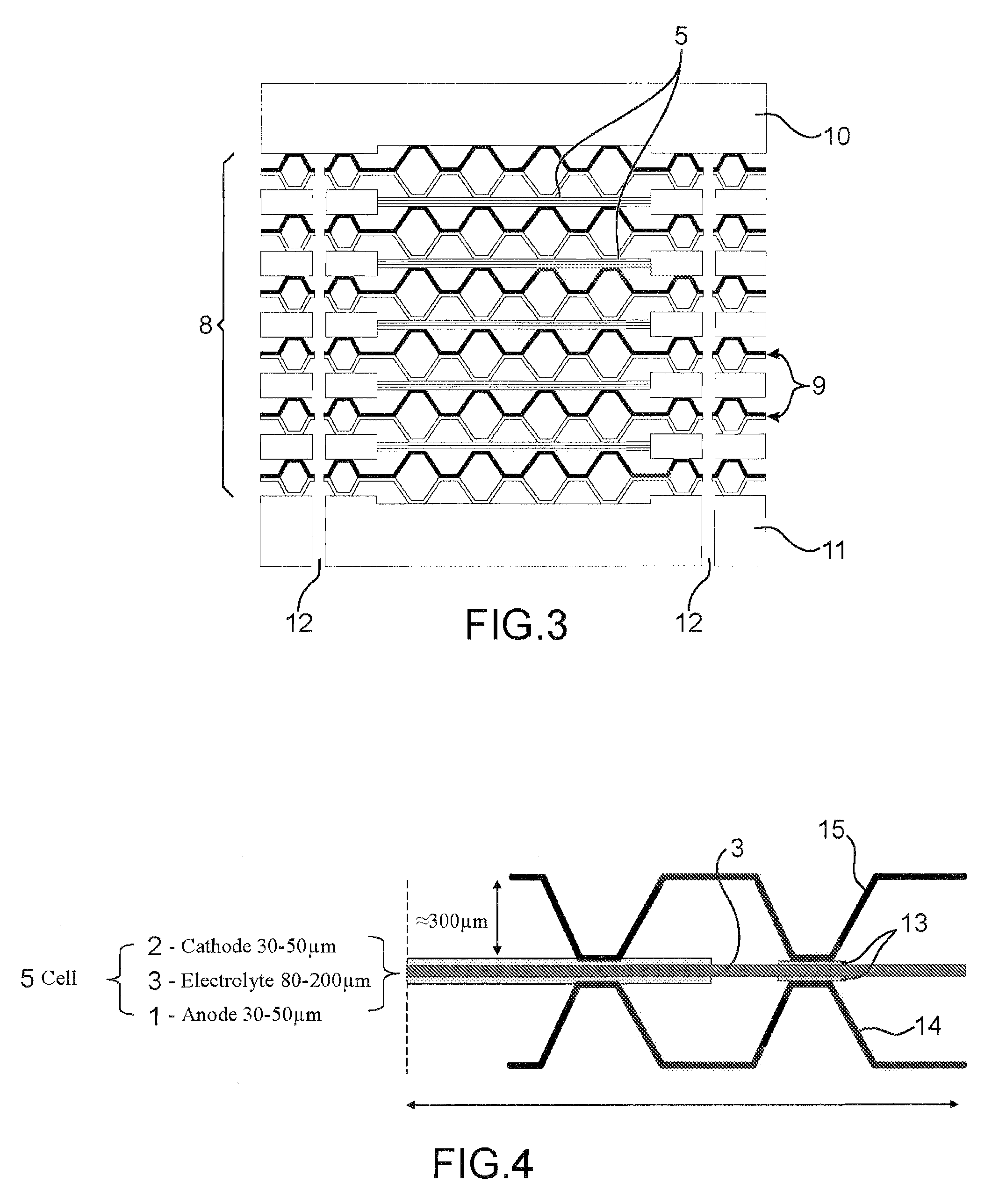
RELATED APPLICATIONS[0001]This application is a U.S. National Phase of International Application No. PCT / EP2010 / 059236, filed Jun. 29, 2010, designating the U.S., and published in French as WO 2011 / 000847 on Jan. 6, 2011 which claims the benefit of French Patent Application No. 0954613 filed Jul. 3, 2009.BACKGROUND OF THE INVENTION[0002]1. Field of the Invention[0003]The invention relates to glass compositions, and more particularly to glass compositions for gaskets, seals of apparatuses operating at high temperatures, for example from 600 to 1000° C. notably from 700 to 900° C.[0004]More specifically, the invention relates to glass compositions for gaskets, seals of a high temperature electrolyzer (<<HTE>>) or of a high temperature fuel cell (Solid Oxide Fuel Cell or SOFC) comprising a stack of elementary cells.[0005]The invention further relates to a method for assembling at least two parts by applying said glass compositions. These parts are notably parts which enter ...

Claims


Application Information

Patent Timeline
Patent Type & Authority Patents(United States)
IPC IPC(8): C03C3/091H01M8/02C25B9/18C03C10/00C03C8/24C03C3/095C03C3/076
CPCC03C3/076C03C3/091C03C3/095C03C8/24C03C10/0009C03C10/0018C25B9/18H01M8/0282Y02E60/50Y02P70/56C25B9/70Y02P70/50
Inventor NONNET, HELENEGRANDJEAN, AGNESVALLAT, CHARLENECOILLOT, DANIELMONTAGNE, LIONEL
Owner COMMISSARIAT A LENERGIE ATOMIQUE ET AUX ENERGIES ALTERNATIVES
Learn More